Automatic reset buffer door hinge

An automatic reset and door hinge technology, applied in door/window accessories, switches with brakes, wing parts, etc. The effect of oil backflow, increasing bearing weight and avoiding stuck state

Pending Publication Date: 2022-03-01
佛山市南海微波通讯设备有限公司
View PDF0 Cites 0 Cited by
  • Summary
  • Abstract
  • Description
  • Claims
  • Application Information

AI Technical Summary

Problems solved by technology

However, using the torsion spring to reset, it is found that the torsion spring with high wire strength is easy to break, while the torsion spring with low strength is easy to relax and cause reset failure.
However, using the central axis to control the closing force may easily lead to insufficient strength of the central axis.
At the same time, the processing of the central shaft is complicated, the manufacturing cost is high, the use is not convenient enough, and it is difficult to promote

Method used


Image

  • Automatic reset buffer door hinge
  • Automatic reset buffer door hinge
  • Automatic reset buffer door hinge

Examples


Embodiment Construction

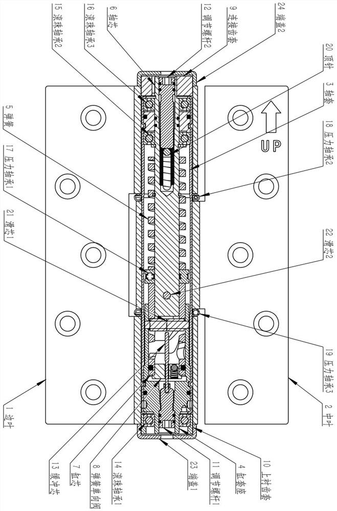
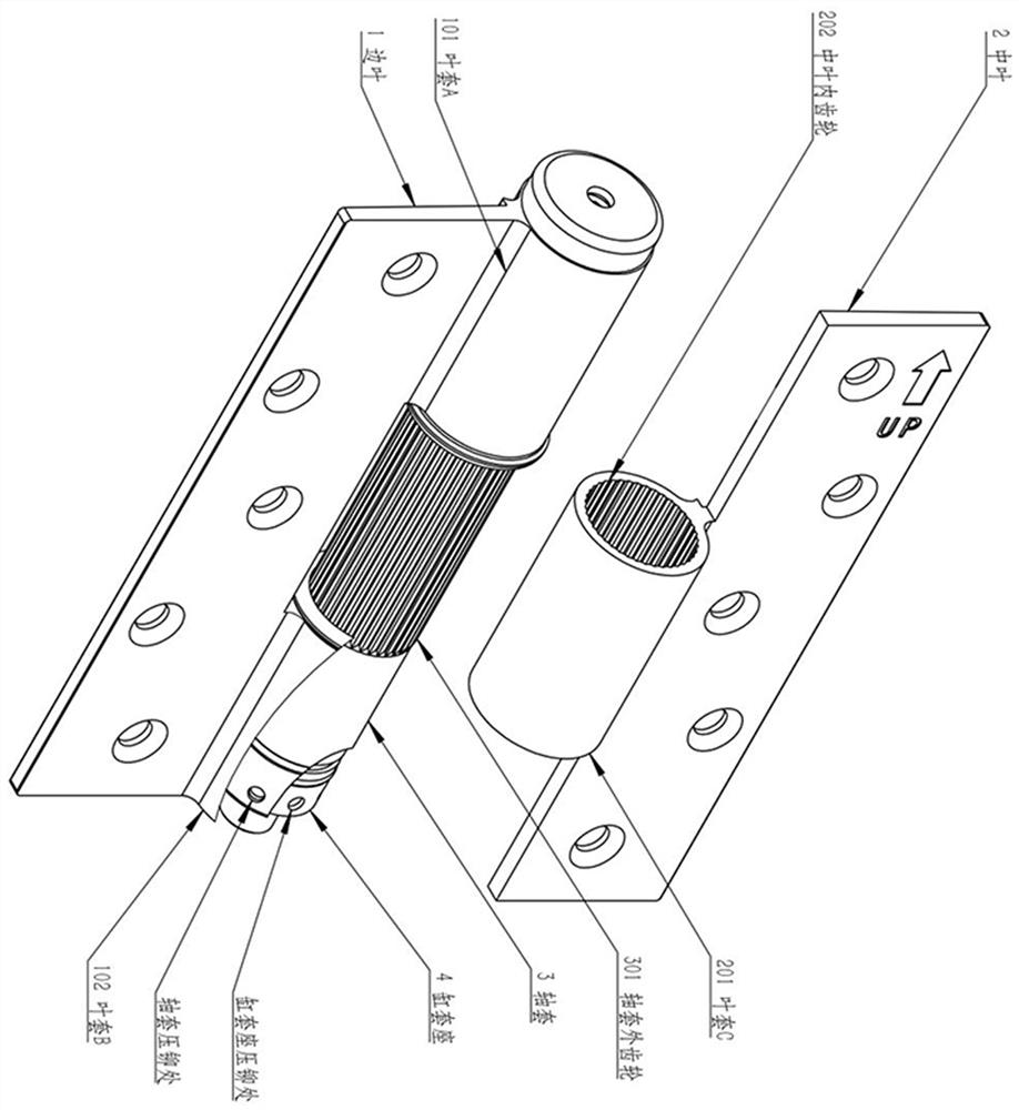
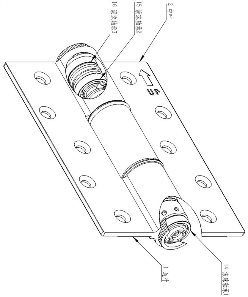
[0015] As shown in Figures 1, 2, 3, and 4, the present invention includes side leaves, middle leaves, pressure springs, shaft sleeves, cylinder sleeves, shaft cores and cylinder cores; The leaf sleeve B is combined with the upper bushing gear sleeve. The inside of the blade sleeve C is the middle leaf internal gear, which is fitted and fixed with the outer gear in the middle part of the shaft sleeve. The blade sleeve A and the blade sleeve C are connected by the pressure bearing 2, and the blade sleeve B and leaf sleeve C are connected by pressure bearing 3, end cover 1 is connected with the upper lining gear sleeve at the bottom, and end cover 2 is connected with the connecting gear sleeve at the top, which together constitute the external structure of the door hinge; the shaft sleeve and the cylinder sleeve The seat is connected by ring-fitting pressure riveting, and the pressure riveting position is at the upper end of the ball bearing shaft 1; the top of the shaft core is c...


PUM


Abstract

The invention discloses an automatic reset buffer door hinge, which can effectively increase the bearing weight and enable the rotation of the door hinge to be smoother through the design of balanced stress of a three-blade sleeve and combined rotation of three ball bearings. And meanwhile, the pressure spring and the spring type single valve are arranged, so that the door hinge can be automatically reset, and a better buffering effect is achieved.

Description

technical field [0001] The invention relates to the field of door and window hardware accessories, and more specifically relates to an automatic reset buffer door hinge. Background technique [0002] At present, the automatic door closing system of most door hinges on the market is mainly based on torsion spring reset, and the door closing force control system is mainly controlled by the pressure regulating screw in the central shaft. However, it is found in actual use that the torsion spring with high wire strength is easy to break when the torsion spring is used for reset, while the torsion spring with low strength is easy to relax and cause reset failure. And adopt central axis to control door-closing strength, also easily cause the intensity deficiency of central axis. At the same time, the processing of the central shaft is complicated, the manufacturing cost is high, and the use is not convenient enough, so it is difficult to popularize. Contents of the invention ...

Claims


Application Information

Patent Timeline
IPC IPC(8): E05D11/10E05D11/00E05F3/22E05F3/20E05F5/10E05F1/12
CPCE05D11/10E05D11/00E05F3/223E05F3/224E05F3/20E05F5/10E05F1/12
Inventor 谭远枝
Owner 佛山市南海微波通讯设备有限公司
Why Eureka
Try Eureka