
Laser emitting device, laser radar comprising same and detection method

A technology of laser emission and laser reflection, applied in the field of laser detection, which can solve the problems of increasing the field of view, unable to meet the needs of use, and limited horizontal FOV.

Pending Publication Date: 2022-03-01
HESAI TECH CO LTD
View PDF0 Cites 0 Cited by
  • Summary
  • Abstract
  • Description
  • Claims
  • Application Information

AI Technical Summary

Problems solved by technology

In this way, the method of changing the light output direction of the laser cannot be used to increase the field of view, resulting in the limitation of the horizontal FOV of the FMCW radar, which cannot meet the needs of the field of automatic driving and other fields.

Method used


Image

  • Laser emitting device, laser radar comprising same and detection method
  • Laser emitting device, laser radar comprising same and detection method
  • Laser emitting device, laser radar comprising same and detection method

Examples


Embodiment Construction

[0070] In the following, only some exemplary embodiments are briefly described. As those skilled in the art would realize, the described embodiments may be modified in various different ways, all without departing from the spirit or scope of the present invention. Accordingly, the drawings and descriptions are to be regarded as illustrative in nature and not restrictive.

[0071] In describing the present invention, it is to be understood that the terms "center", "longitudinal", "transverse", "length", "width", "thickness", "upper", "lower", "front", " Back", "Left", "Right", "Vertical", "Horizontal", "Top", "Bottom", "Inner", "Outer", "Clockwise", "Counterclockwise", etc. or The positional relationship is based on the orientation or positional relationship shown in the drawings, which is only for the convenience of describing the present invention and simplifying the description, rather than indicating or implying that the referred device or element must have a specific orie...


PUM


Abstract

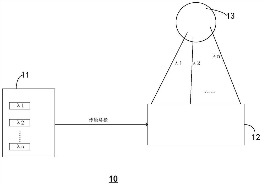
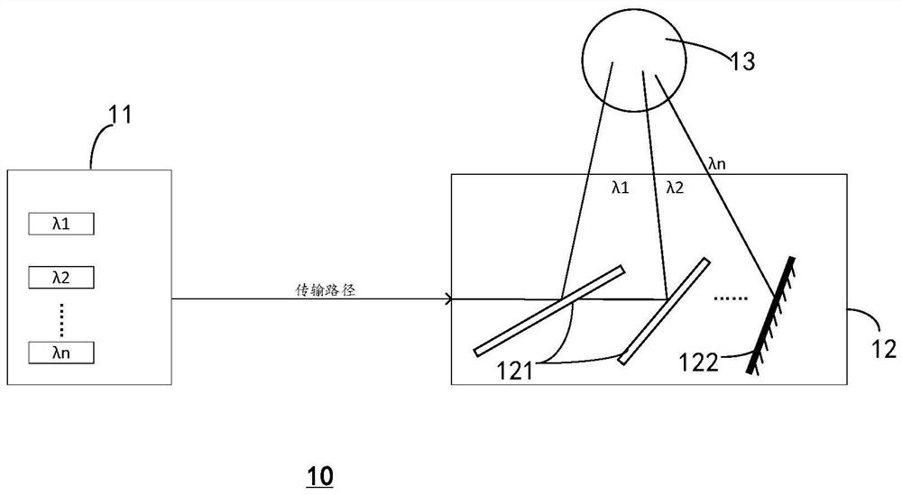
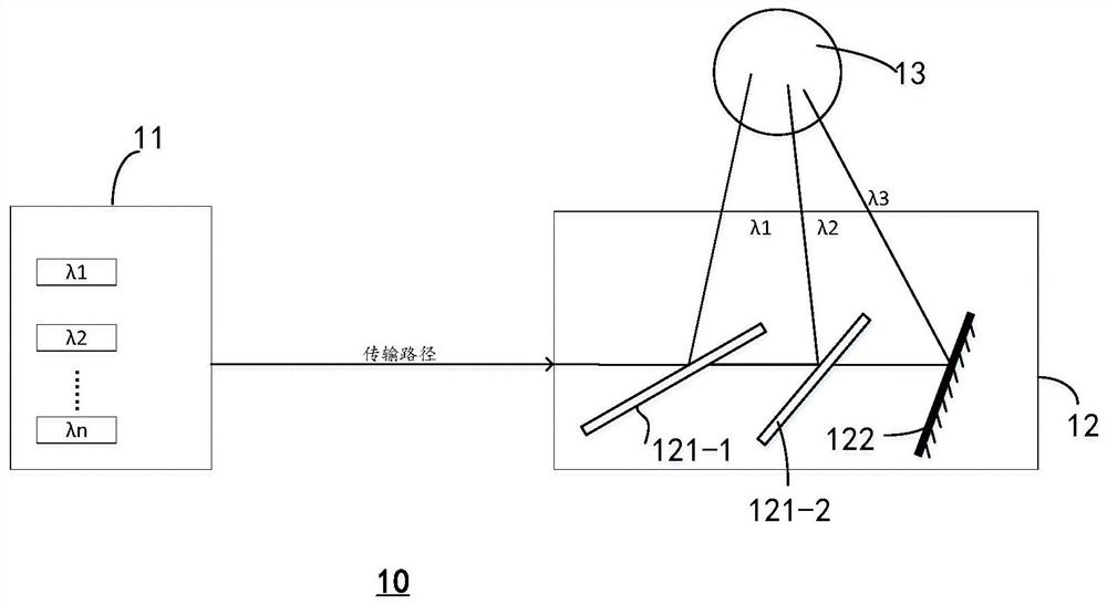
The invention provides a laser emitting device which comprises an emitting unit which is configured to be capable of emitting a plurality of continuous lasers with different wavelengths in sequence; the light splitting unit is arranged at the downstream of a light path of the emitting unit and is configured to deflect the continuous lasers with the different wavelengths at different angles according to the wavelengths of the continuous lasers; and the scanning unit is arranged at the downstream of the light path of the light splitting unit and is configured to receive the deflected continuous laser and scan and emit the continuous laser to a target space so as to cover a plurality of view field areas corresponding to the plurality of wavelengths.

Description

technical field [0001] The present invention generally relates to the technical field of laser detection, and in particular to a laser emitting device, a laser radar including the same, and a detection method using the laser radar. Background technique [0002] Frequency Modulation Continuous Wave (FMCW) radar refers to a continuous wave radar whose transmission frequency is modulated by a specific signal. The FMCW radar emits continuous waves with changing frequencies during the frequency sweep period. The echo reflected by the target object has a certain frequency difference with the transmitted signal. The radial velocity and distance of the target can be obtained by processing the measured frequency difference between the two. The frequency of the difference frequency signal is low, generally kHz, so the hardware processing is relatively simple, suitable for data acquisition and digital signal processing; moreover, the required continuous wave transmission power peak val...

Claims


Application Information

Patent Timeline
IPC IPC(8): G01S7/481
CPCG01S7/4814G01S7/4817
Inventor 潘政清孙恺向少卿
Owner HESAI TECH CO LTD
Learn More