
A large field of view small aberration lobster eye imaging system

An imaging system and lobster eye technology, applied in the field of detection, can solve the problems of difficult processing of spherical detectors, high manufacturing costs, and single working spectrum, so as to improve the working capacity of the system, compress the size and weight of the system, and reduce the system image. poor effect

Active Publication Date: 2022-07-12
BEIJING INSTITUTE OF TECHNOLOGYGY
View PDF7 Cites 0 Cited by
  • Summary
  • Abstract
  • Description
  • Claims
  • Application Information

AI Technical Summary

Problems solved by technology

However, the system has a single working spectrum, only works in the infrared band, and has no response to visible light targets, and the spherical detector is difficult to process, and the manufacturing cost is high. It is difficult to popularize and practical with the current domestic technology level.

Method used


Image

  • A large field of view small aberration lobster eye imaging system
  • A large field of view small aberration lobster eye imaging system
  • A large field of view small aberration lobster eye imaging system

Examples


Embodiment 1

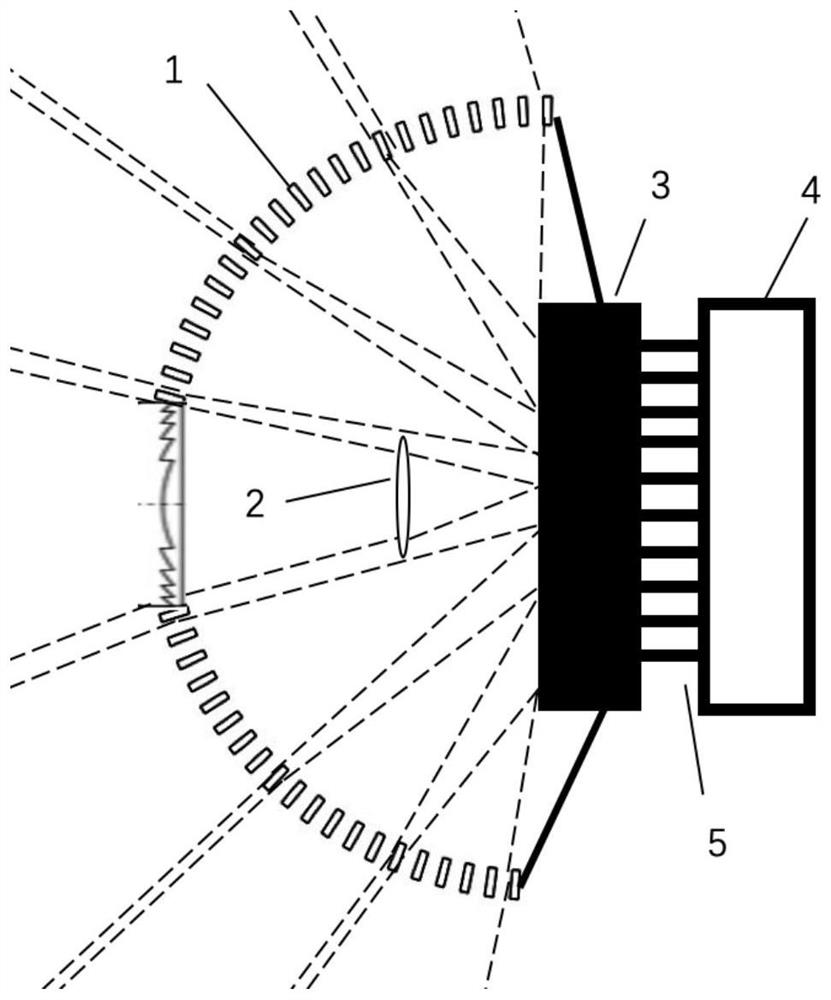
[0030] A large field of view small aberration lobster eye imaging system, such as figure 2 As shown, it includes: an objective lens 1 , a detector 3 , an information processing and regulation system 4 and a posture adjustment mechanism 5 .

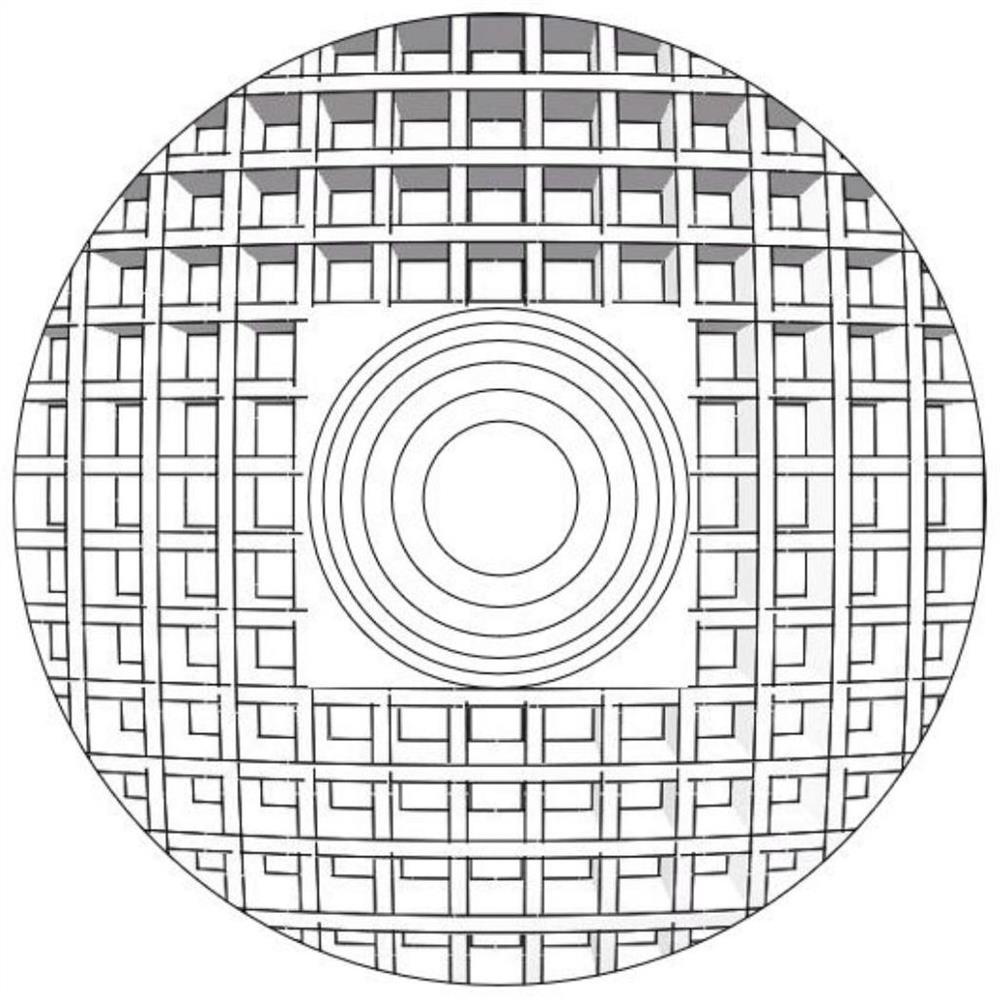
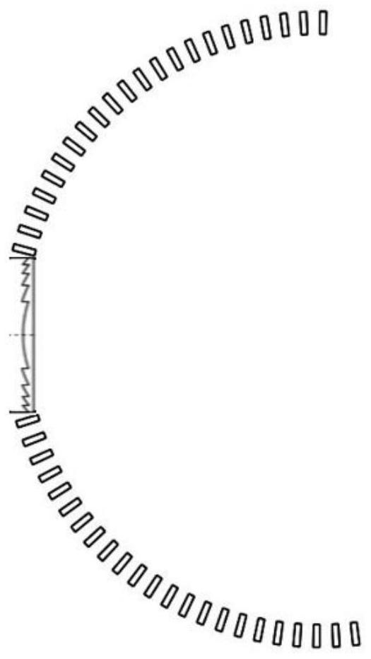
[0031] The objective lens 1 of the target detection system of the present invention adopts a lobster eye structure. As shown in Figure 1(a), each ommatidia of the objective lens 1 is a tiny quadrangular prism; several tiny quadrangular prisms are closely arranged to form a hemisphere; As shown in Figure 1(b), the hemispherical surface can be regarded as composed of three-dimensional rings that are close to each other but with different radii. The three-dimensional ring is formed by a number of tiny quadrangular pyramids wound around one circle; the ring is a part of the three-dimensional spherical surface. Instead of a plane structure, the radius of curvature of the solid spherical surface is R.

[0032] The quadrangular platform is a hol...

Embodiment 2

[0038] A lobster eye imaging system with a large field of view and small aberration, comprising: a bionic diffractive objective lens 1 , a relay lens group 2 , a detector 3 , an information processing and control system 4 and a posture adjustment mechanism 5 .

[0039] On the basis of Example 1, the area at the center of the objective lens is replaced with a single-layer or multi-layer harmonic diffractive lens structure to form a bionic diffractive objective lens. By using different orders of light, the harmonic diffractive surface type can make visible light and infrared wavelengths. Part of the resonant wavelength light has the same focal length and high diffraction efficiency, so that the axial chromatic aberration in the visible and infrared bands can be corrected. Then it is transmitted to the relay lens group 2, so that the radiated light of the target finally converges at a point on the image plane. In the non-center area of ​​the bionic diffractive objective lens 1, t...


PUM


Abstract

The invention discloses a lobster eye imaging system with a large field of view and a small aberration. Each small eye of an objective lens is a tiny quadrangular pyramid, the inner wall of the tiny quadrangular pyramid is a free curved surface, and the hemispherical objective lens can be regarded as composed of It is composed of three-dimensional rings that are close to each other but with different radii. The three-dimensional ring is formed by a number of tiny quadrangular pyramids. The side lengths near the center of the sphere are equal, and the angle between the sides of the quadrangular prism gradually decreases, which can make the focal length of the objective change to a certain extent. The closer the focal length of the microchannel to the center is, the longer the focal length; The image plane at the distance R is a plane rather than a sphere, which realizes high-resolution, multi-spectral, and planar imaging of the target in a large field of view, solves the problem that the working spectrum of the system is limited by optical materials, and effectively eliminates the traditional The unavoidable large field curvature of the lobster eye structure imaging reduces the system aberration, improves the uniformity of the image surface energy, can effectively compress the size and weight of the system, and has the effect of significantly improving the system's working ability and realizing application deployment.

Description

technical field [0001] The invention belongs to the technical field of detection, in particular to a lobster eye imaging system with large field of view and small aberration. Background technique [0002] In the work scenarios such as target warning and post-disaster search and rescue, the detection field of view, the number of channels and the imaging resolution of the optical system are constantly improving. The larger the field of view that the optical system can monitor and detect, the sooner the system can find the target, which will buy a lot of time for subsequent defense measures or rescue work; the wider the working spectrum of the optical system and the higher the imaging resolution, the better The larger the amount of information, the more conducive to the accurate classification and identification of the target, reduce the false alarm rate of the system, and improve the accuracy of the system identification. However, as we all know, the field of view and imaging...

Claims


Application Information

Patent Timeline
Patent Type & Authority Patents(China)
IPC IPC(8): G01J3/28G01J3/02G02B5/04G02B5/18
CPCG01J3/2823G01J3/0205G02B5/045G02B5/1814G01J2003/2826
Inventor 常军钟乐李轶庭黄翼姜会林宋大林
Owner BEIJING INSTITUTE OF TECHNOLOGYGY
Learn More