
Transmission circuit for Ethernet

A transmission circuit and Ethernet technology, applied in the direction of transformer/inductor coil/winding/connection, etc., can solve the problems of high production cost, the Ethernet system is prone to surge interference, and the poor adaptability of Ethernet transformer capacity changes. Achieve the effect of high environmental adaptability

Inactive Publication Date: 2022-03-01
SINITIAL TECH INC
View PDF0 Cites 0 Cited by
  • Summary
  • Abstract
  • Description
  • Claims
  • Application Information

AI Technical Summary

Problems solved by technology

[0002] Traditional network transformers for Ethernet (hereinafter referred to as "Ethernet transformers") include transformers with center taps, so they must be produced by manual winding, which makes traditional Ethernet transformers less adaptable to changes in production capacity. Poor and relatively expensive to produce
In addition, traditional Ethernet transformers do not have the function of surge protection, which makes the Ethernet system often unable to operate in environments that are susceptible to surge interference (such as lightning strikes, static electricity, or switching actions of power supplies with other loads in the same circuit). Effectively operates such that Ethernet service has to be interrupted

Method used


Image

  • Transmission circuit for Ethernet
  • Transmission circuit for Ethernet
  • Transmission circuit for Ethernet

Examples


Embodiment Construction

[0040] The following examples are used to illustrate the technical content of the present invention, but not to limit the scope of the present invention. It should be noted that in the following embodiments and drawings, elements irrelevant to the present invention have been omitted and not shown, and the dimensional relationship among the elements in the drawings is only for easy understanding, and is not intended to limit the actual ratio. In this article, terms such as "first", "second", "third", and "fourth" added before some elements are only used to distinguish each element, and are not used to limit the order of each element relation.

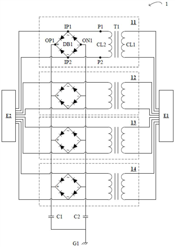
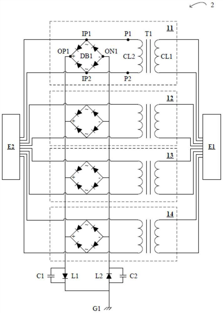
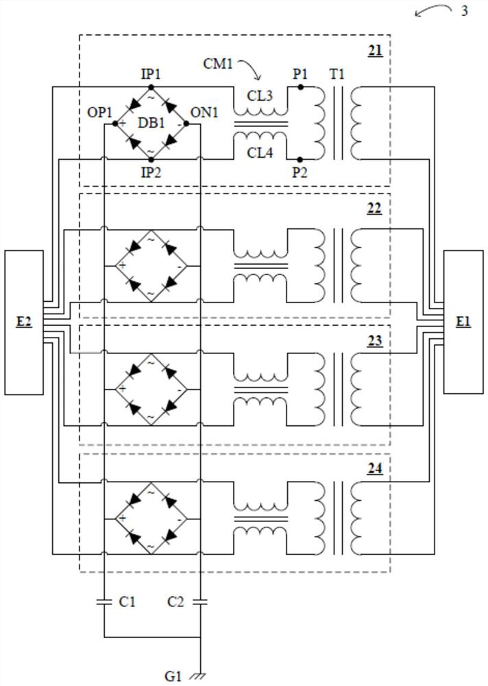
[0041] figure 1 It is a schematic diagram of an implementation of the Ethernet transmission circuit of the present invention. refer to figure 1 , a transmission circuit 1 for Ethernet basically includes four sets of transmission sub-circuits 11 , 12 , 13 , 14 . Since the signals transmitted in Ethernet are generally designed to be tr...


PUM

PropertyMeasurementUnit
Inductance valueaaaaaaaaaa

Abstract

A transmission circuit for Ethernet comprises four transmission sub-circuits, a first capacitor and a second capacitor. Each transmission sub-circuit is coupled between an Ethernet physical layer device and an Ethernet connection device, and each transmission sub-circuit is used for transmitting a pair of differential mode signals of the Ethernet. Each transmission sub-circuit comprises a diode bridge and a transformer. A first input terminal and a second input terminal of the diode bridge are both coupled to the Ethernet connection device. The transformer comprises a first coil and a second coil, two ends of the first coil are coupled to the Ethernet physical layer equipment, and two ends of the second coil are respectively coupled to the first input end and the second input end. The first capacitor is coupled to the ground and the positive output end of each diode bridge. The second capacitor is coupled to the ground and the cathode output end of each diode bridge.

Description

technical field [0001] The invention relates to a transmission circuit for Ethernet. More specifically, the Ethernet transmission circuit of the present invention can replace a traditional Ethernet transformer, and provide functions of signal coupling, DC isolation and surge protection for Ethernet transmission. Background technique [0002] Traditional network transformers for Ethernet (hereinafter referred to as "Ethernet transformers") include transformers with center taps, so they must be produced by manual winding, which makes traditional Ethernet transformers less adaptable to changes in production capacity. Poor and relatively expensive to produce. In addition, the traditional Ethernet transformer does not have the function of surge protection, which makes the Ethernet system often unable to operate in environments that are susceptible to surge interference (such as lightning strikes, static electricity, or switching actions of power supplies of other loads in the sa...

Claims


Application Information

Patent Timeline
IPC IPC(8): H01F27/28
CPCH01F27/28
Inventor 林旻泛
Owner SINITIAL TECH INC
Learn More