High-performance combined structure residence system
A combined structure and high-performance technology, which is applied in the direction of residential buildings, building components, building structures, etc., can solve the problems of low flexural bearing capacity of round steel columns and inconvenient connection of nodes, so that the quality of pouring can be easily guaranteed and improved. The effect of connection efficiency and low production cost
- Summary
- Abstract
- Description
- Claims
- Application Information
AI Technical Summary
Problems solved by technology
Method used
Image
Examples
Embodiment 1
[0084] A high-performance composite structure residential system provided by this embodiment includes: beams, columns, shear walls, and floors. The column body includes several combined column sections 30 that are fixedly connected up and down.
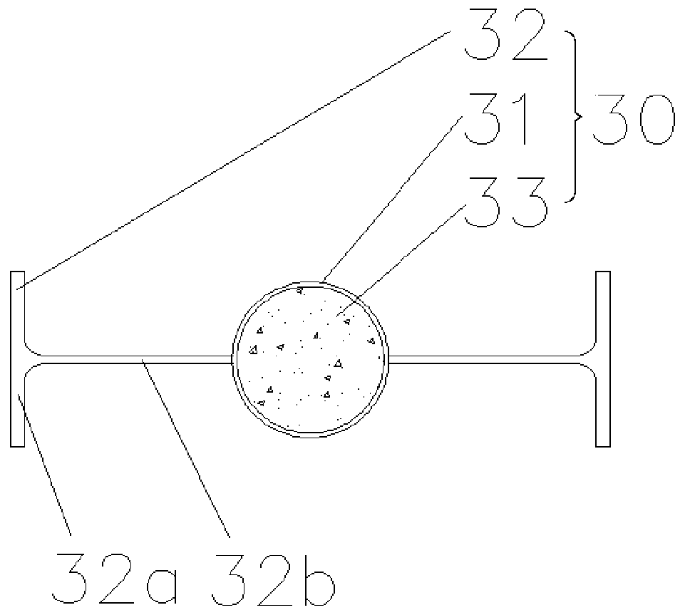
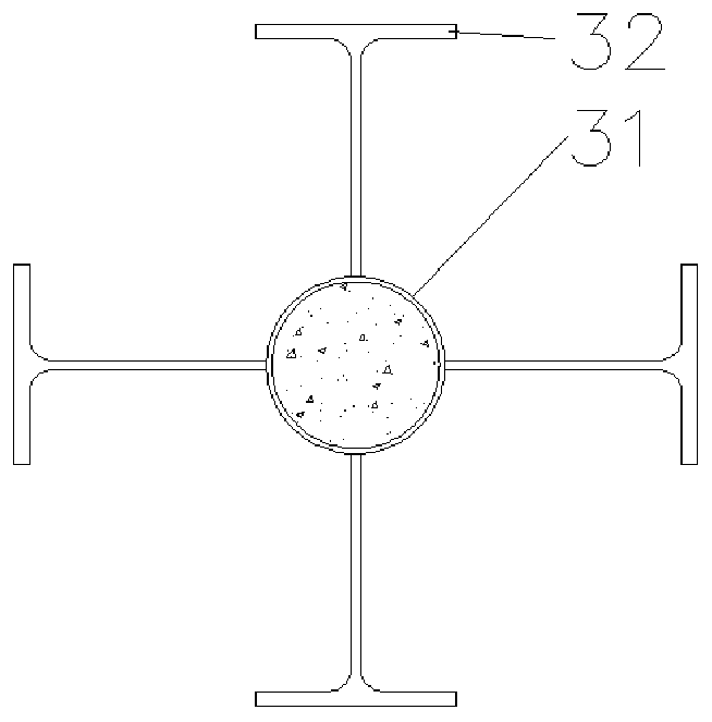
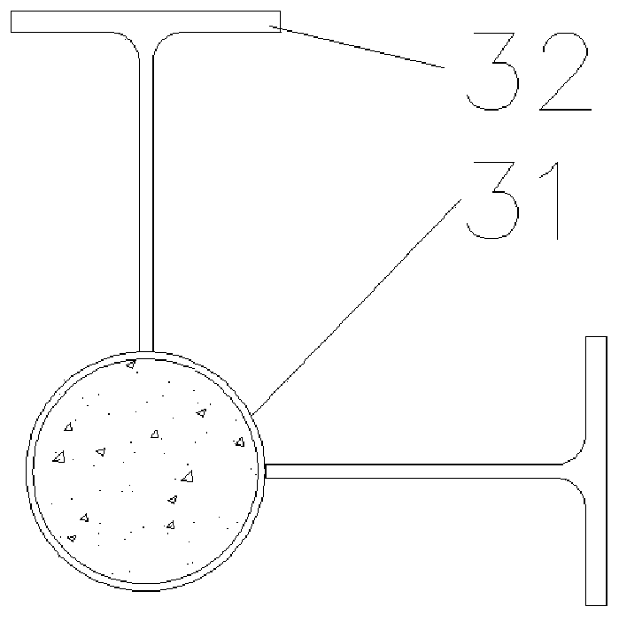
[0085] like Figure 1-Figure 4 As shown, a composite column section 30 provided in this embodiment includes a round steel pipe 31 and 2-4 T-shaped steels 32; The webs of the T-shaped steel 32 are arranged at intervals, and the opposite end of the web of the T-shaped steel 32 and the flange are fixedly connected to the outer wall of the round steel pipe 31;
[0086] Among them, several T-shaped steels 32 are arranged in various ways, such as figure 1 As shown, there are two T-shaped steels 32, and the webs of the two T-shaped steels 32 are located on the same diameter of the round steel pipe 31 to form a straight-line shape. like image 3 As shown, there are two T-shaped steels 32, and the webs of the two T-shaped steels 32 are per...
Embodiment 2
[0092] The present embodiment discloses a high-performance composite structure residential system, including beams, columns, shear walls and floors. The column body is the combined column section 30 in Example 1.
[0093] like Figure 5 As shown, the combined column section 30 is embedded in the wall body 4 as a column body; the T-shaped steel flange near the outdoor side in the combined column section 30 is the outer flange 3a, and the outer flange 3a is parallel to the wall surface of the wall body 4 set; the outer end face of the outer flange 3a is coated with an outer anti-corrosion layer (not shown); the outer side of the anti-corrosion layer of the outer flange is laid with several layers of glass wool boards 10 for blocking the combined column section 30 as a thermal bridge on the wall Heat flow is transferred between the indoor and outdoor sides of the body.
[0094] While effectively eliminating the thermal bridge effect at the combined column section 30 and improvi...
Embodiment 3
[0109] This embodiment discloses a high-performance composite structure housing system, and the difference from Embodiment 4 is that the beam in this embodiment is a partially clad steel-concrete composite member.
[0110] like Image 6 and Figure 7 As shown, the partially clad steel-concrete composite member in this embodiment includes: a first side steel plate 100 , a second side steel plate 200 , a stud 500 , a repair welding steel plate 400 , a stiffening steel plate 300 , a steel frame 600 and a concrete 700 .
[0111] The first side steel plate 100 and the second side steel plate 200 are arranged in parallel and spaced apart; the two stiffening steel plates 300 are arranged at intervals between the first side steel plate 100 and the second side steel plate 200, and the two ends of the stiffening steel plate 300 are respectively connected to the first side steel plate 100. It is fixedly connected with the second side steel plate 200 .
[0112] The two stiffened steel p...
PUM
 Abstract
Description
Claims
Application Information
 - R&D
- Intellectual Property
- Life Sciences
- Materials
- Tech Scout
- Unparalleled Data Quality
- Higher Quality Content
- 60% Fewer Hallucinations
Browse by: Latest US Patents, China's latest patents, Technical Efficacy Thesaurus, Application Domain, Technology Topic, Popular Technical Reports.
© 2025 PatSnap. All rights reserved.Legal|Privacy policy|Modern Slavery Act Transparency Statement|Sitemap|About US| Contact US: help@patsnap.com


