Concrete Steel Tube Column-Steel Beam External Diaphragm Joint Structure and Its Construction Method

A technology for concrete-filled steel tubular columns and concrete structures, which is applied to building components, building structures, earthquake-proof and other directions to achieve the effects of enhanced combined action, reasonable design, and reduced size

Active Publication Date: 2017-03-29
CHANGAN UNIV
View PDF5 Cites 0 Cited by
  • Summary
  • Abstract
  • Description
  • Claims
  • Application Information

AI Technical Summary

Problems solved by technology

[0005] The technical problem to be solved by the present invention is to provide a concrete-filled steel tube column-steel girder external diaphragm joint structure, which has simple structure, reasonable design, easy construction, good use effect and clear force transmission. , which can effectively alleviate the stress concentration and deformation concentration problems existing in the CFST column-steel beam joint, and has excellent seismic performance

Method used


Image

  • Concrete Steel Tube Column-Steel Beam External Diaphragm Joint Structure and Its Construction Method
  • Concrete Steel Tube Column-Steel Beam External Diaphragm Joint Structure and Its Construction Method
  • Concrete Steel Tube Column-Steel Beam External Diaphragm Joint Structure and Its Construction Method

Examples


Embodiment 1

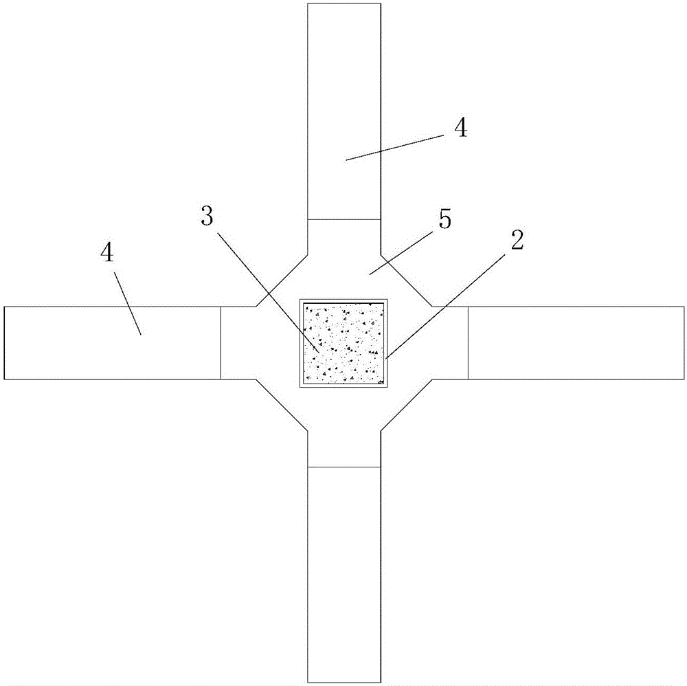
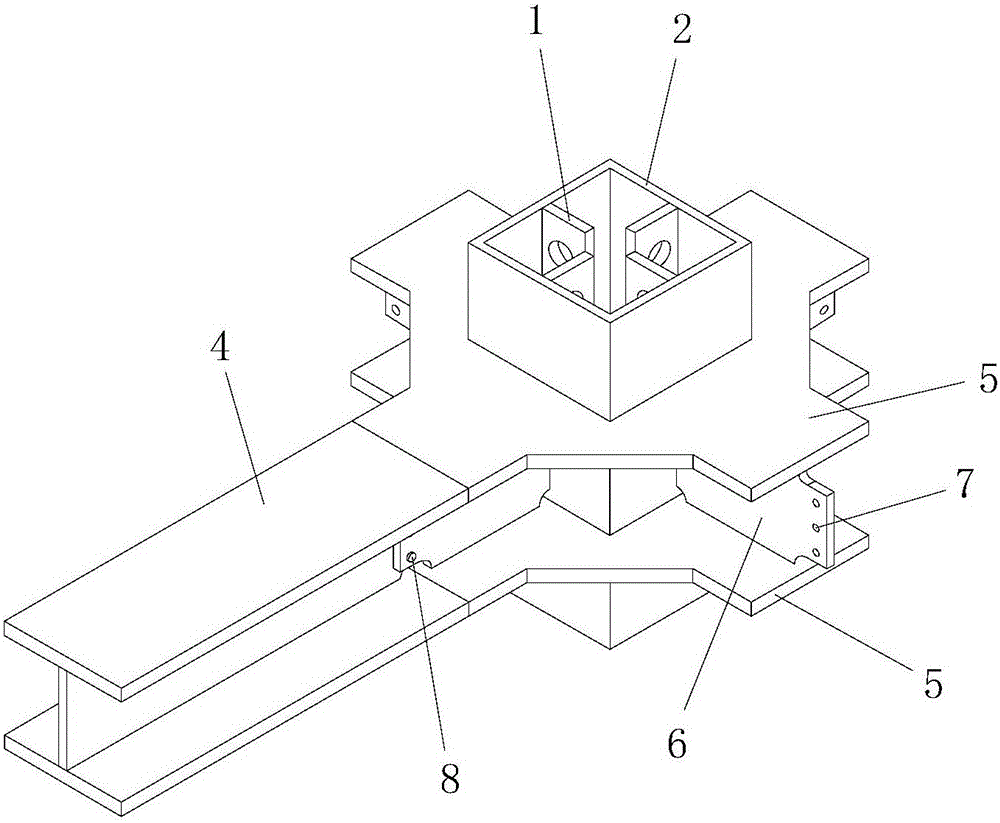
[0061] Such as figure 1 , figure 2 , image 3 , Figure 4 and Figure 5 The concrete-filled steel tube column-steel beam outer diaphragm joint structure shown includes a steel tube concrete column, a steel beam 4 located outside the steel tube concrete column, and a beam connected between the steel tube concrete column and the steel beam 4 The column connection structure, the steel pipe concrete column and the steel beam 4 are arranged vertically.

[0062] The concrete-filled steel pipe column includes a rectangular steel pipe column 2, four groups of longitudinal ribs 1 with openings arranged on the four inner walls of the rectangular steel pipe column 2, and a core concrete structure 3 filled in the rectangular steel pipe column 2. The perforated longitudinal ribs 1 are all poured in the core concrete structure 3, and the structure and size of all perforated longitudinal ribs 1 in the four groups of perforated longitudinal ribs 1 are the same; each group of perforated l...

Embodiment 2

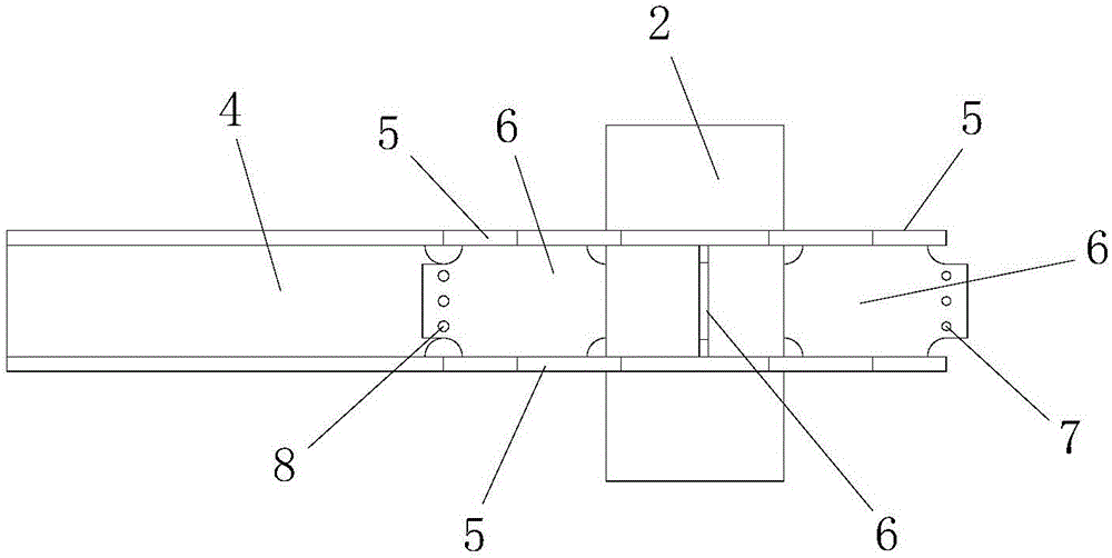
[0104] In this example, if Figure 7 , Figure 8 , Figure 9 and Figure 10 As shown, the adopted CFST column-steel girder outer diaphragm node structure is different from that of Embodiment 1 in that: the web connecting plate 6 and the steel girder 4 are connected by welding, and the four The perforated longitudinal ribs 1 are respectively arranged in the middle of the four inner side walls of the rectangular steel pipe column 2 .

[0105] In this embodiment, the structure and connection relationship of the remaining parts of the steel pipe concrete column-steel beam outer diaphragm joint structure are the same as those in Embodiment 1.

[0106] In this embodiment, the construction method of the steel pipe concrete column-steel girder external diaphragm joint structure is different from that in Embodiment 1 in that: when connecting the steel girders in step 3, the steel girder 4 and the web connection plate 6 are connected by Connected by welding.

[0107] In this embodi...

Embodiment 3

[0109] In this example, if Figure 11 , Figure 12 , Figure 13 and Figure 14 As shown, the adopted CFST column-steel girder outer diaphragm node structure is different from that of Embodiment 1 in that it also includes m stirrups 9 arranged on the four groups of longitudinal ribs 1 with openings from top to bottom. , the stirrups 9 of the m road are arranged in parallel, and the stirrups 9 of the m road are arranged perpendicular to the rectangular steel pipe column 2, wherein m is a positive integer and m≥3; the stirrups 9 of the m road are all poured in the core Inside the concrete structure 3;

[0110] The number of through holes 10 opened on the strip steel ribs is m, and the stirrups 9 of the m roads are respectively from the m through holes 10 opened on each of the strip steel ribs. through. Such as Figure 15 As shown, the through hole 10 is a slot-shaped hole.

[0111] In this embodiment, m=5.

[0112] During actual construction, the value of m can be adjuste...


PUM

PropertyMeasurementUnit
thicknessaaaaaaaaaa

Abstract

The invention discloses a concrete-filled steel pipe column-steel girder outer diaphragm joint structure and a construction method thereof. The beam-column connection structure, the concrete-filled steel tube column and the steel beam are arranged vertically; the concrete-filled steel tube column includes a rectangular steel tube column, four sets of open longitudinal ribs and a core concrete structure; the beam-column connection structure includes an upper outer diaphragm and a lower outer diaphragm; The upper outer end of the steel beam is tightly connected to the upper outer diaphragm and the lower outer end is tightly connected to the lower outer diaphragm; the construction method of the node structure includes steps: 1. Welding the longitudinal rib with the hole and the rectangular steel pipe column; 2. 1. Beam-column connection structural welding; 3. Steel beam connection; 4. Concrete pouring. The invention has the advantages of reasonable design, convenient construction, good use effect, clear force transmission, can effectively alleviate the problems of stress concentration and deformation concentration existing in the steel pipe concrete column-steel beam joint, and has excellent seismic performance.

Description

technical field [0001] The invention belongs to the technical field of building construction, and in particular relates to a concrete-filled steel tube column-steel girder outer diaphragm joint structure and a construction method thereof. Background technique [0002] With the rapid development of economy and society, land resources in large and medium cities are constantly decreasing, and medium and low-rise buildings can no longer meet the functional requirements of cities and people's ever-increasing living needs. Therefore, high-rise and super high-rise buildings are constantly being built in large and medium-sized cities in my country. Most of the large and medium-sized cities in my country are located in seismic fortified areas, so how to improve the seismic performance of high-rise and super high-rise buildings has become a hot topic in the field of construction engineering. In the frame structure, the column-beam connection node (also known as the beam-column node) ...

Claims


Application Information

Patent Timeline
Patent Type & Authority Patents(China)
IPC IPC(8): E04B1/58E04G21/00E04B1/98
CPCE04B1/58E04B1/98E04G21/00
Inventor 朱伟庆刘永健龙刚张瑑芳傅梅珍崔越衡江峰
Owner CHANGAN UNIV
Why Eureka
Try Eureka