Intelligent low-voltage power distribution cabinet capable of being remotely controlled
A remote control, power distribution cabinet technology, applied in substation/distribution device housing, electrical components, substation/switch layout details, etc., can solve problems such as temperature rise and failure, and achieve the effect of preventing blowing dust from entering
- Summary
- Abstract
- Description
- Claims
- Application Information
AI Technical Summary
Problems solved by technology
Method used
Image
Examples
Embodiment 1
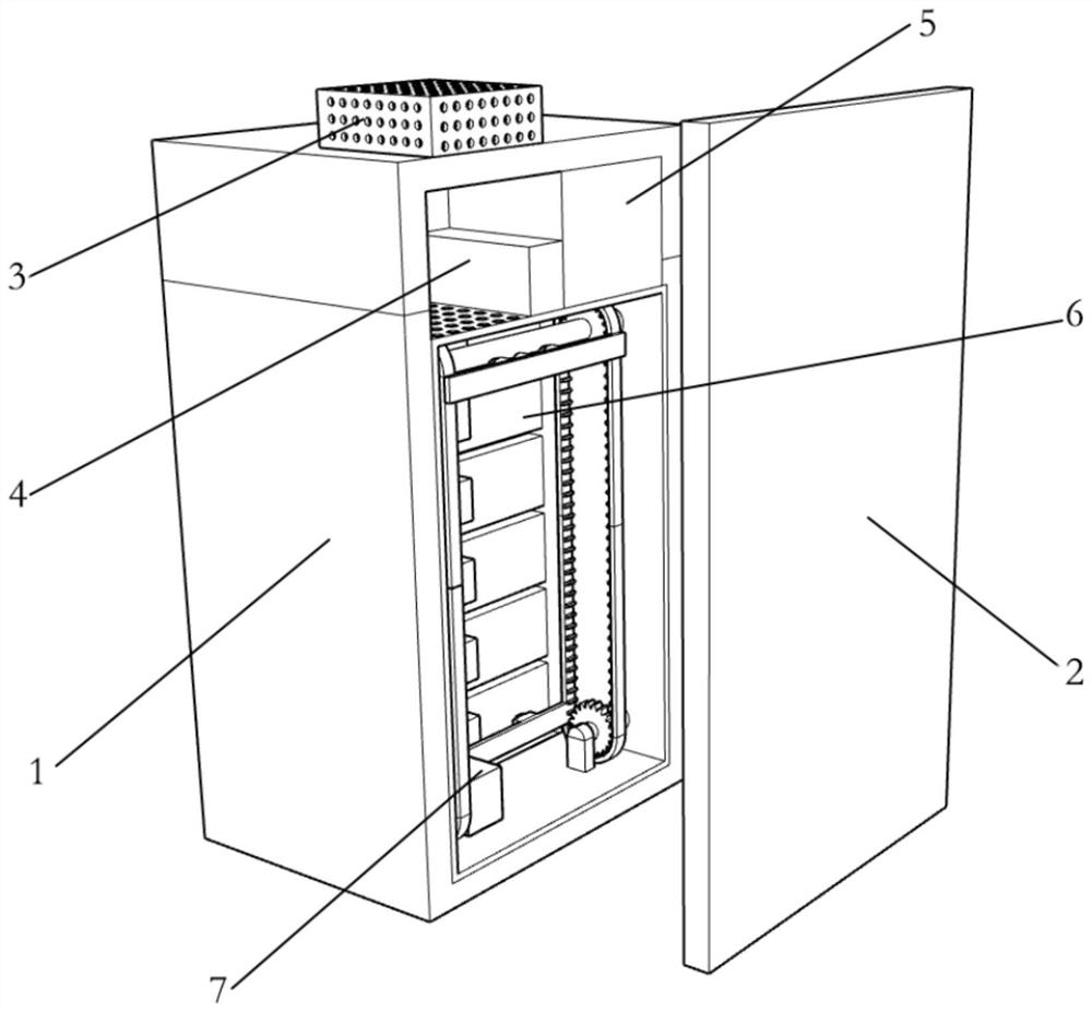
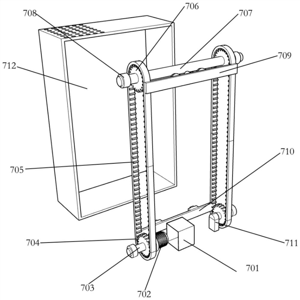
[0027] Embodiment one: refer to figure 1 and figure 2 , the present invention provides a remote-controllable intelligent low-voltage power distribution cabinet, including a main body 1, a cabinet door 2, a busbar room 5, and a functional unit room 6, and also includes:
[0028] Ventilation and cooling mechanism 3: installed on the top of the main body 1, and fixedly connected with the main body 1;
[0029] Bus detection mechanism 4: installed on the side of the bus chamber 5, and fixedly connected with the bus chamber 5;
[0030] Detection movement mechanism 7: installed inside the main body 1 and fixedly connected with the main body 1;
[0031] refer to Figure 4 The ventilation and cooling mechanism 3 includes an upper fixed cabinet 301, a filter screen 302, a fan motor 303, a fan shaft 304, a fixed rod 305, and a fan blade 306. The top of the main body 1 is fixedly connected with an upper fixed cabinet 301, and the top of the upper fixed cabinet 301 is provided There i...
Embodiment 2
[0037] refer to Figure 5 , the two sides inside the main body 1 are provided with avoidance grooves, the limit plate 8 is movably connected in the avoidance groove of the main body 1, and the side of the limit plate 8 away from the avoidance groove of the main body 1 is fixedly connected with the fixed box 712, through the limit The plate 8 is placed in the avoidance groove of the main body 1, so that the fixed box 712 is connected with the limit plate 8, so that the fixed box 712 will not be easily shaken by force, and the stability when holding the equipment is stable. Embodiment 2 and The difference of the first embodiment is that: the side of the main body 1 is provided with an avoidance groove, and the position-limiting plate 8 moves in the avoidance groove of the main body 1, thereby helping to fix the position of the fixing box 712 and ensuring the position of the fixing box 712. The stability of the location.
Embodiment 3
[0039] refer to Figure 6 , the fixed box 712 and the bottom end of the main body 1 are provided with a threaded hole, the fixed box 712 and the threaded hole of the main body 1 are movably connected with a threaded rod 9, and the top of the threaded rod 9 is fixedly connected with the turntable 10, and the main body is connected by the threaded rod 9. 1 is fixed with the fixed box 712, so that the position of the fixed box 712 will not move, and the operation of the equipment can always be kept stable. When maintenance is required, it is only necessary to turn the turntable 10 to turn the threaded rod 9 out. The operation is simple, and the third embodiment The difference from Embodiment 1 is that the fixed box 712 is connected to the main body 1 through the threaded rod 9, so that the fixed box 712 will not move after being fixed, and the threaded rod 9 can be easily rotated by turning the turntable 10, and the operation is more labor-saving.
PUM
 Abstract
Description
Claims
Application Information
 - R&D
- Intellectual Property
- Life Sciences
- Materials
- Tech Scout
- Unparalleled Data Quality
- Higher Quality Content
- 60% Fewer Hallucinations
Browse by: Latest US Patents, China's latest patents, Technical Efficacy Thesaurus, Application Domain, Technology Topic, Popular Technical Reports.
© 2025 PatSnap. All rights reserved.Legal|Privacy policy|Modern Slavery Act Transparency Statement|Sitemap|About US| Contact US: help@patsnap.com


