Permanent magnet motor

A permanent magnet motor and stator technology, applied to synchronous motors with stationary armatures and rotating magnets, electrical components, electromechanical devices, etc., can solve the problems of poor motor performance, jitter, movement, and large accumulated errors, etc. Achieve easy accuracy requirements, reduce processing difficulty, and reduce concentricity errors

Active Publication Date: 2022-03-01
HANGZHOU NEW HENGLI ELECTRONICS MACHINE MFG
View PDF6 Cites 0 Cited by
  • Summary
  • Abstract
  • Description
  • Claims
  • Application Information

AI Technical Summary

Problems solved by technology

[0004] In this way, the overall cumulative error is relatively large, and it is difficult for the rotor / rotating shaft to maintain a high degree of concentricity with the stator, resulting in poor operating performance of the motor, and problems such as jitter and movement are more likely to occur

Method used


Image

  • Permanent magnet motor
  • Permanent magnet motor
  • Permanent magnet motor

Examples


Embodiment 1

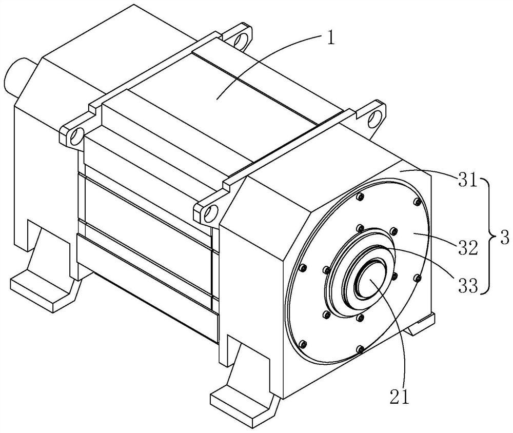
[0043] refer to figure 1 and figure 2 A permanent magnet motor includes a stator 1, a rotor 2 and an end cover 3, the end cover 3 is welded to the end face of the stator 1, the rotor 2 is connected with a rotating shaft 21, and the rotating shaft 21 is installed on the end cover 3.

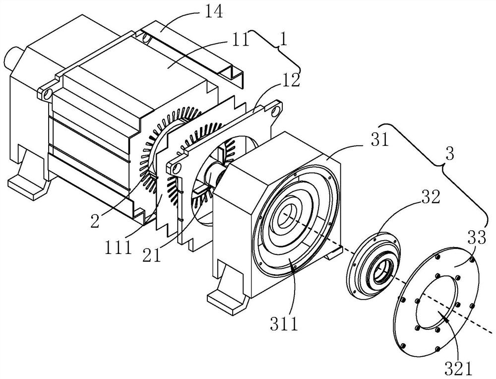
[0044] The stator 1 includes a body 11 and an end plate 12, wherein the body 11 is formed by stacking and welding a plurality of unit pieces 111. The axial projection of the body 11 is polygonal, and a V-shaped groove 13 is recessed in the area where the corners of the polygon are located. In this implementation, the projection takes a regular quadrilateral as an example, a V-shaped groove 13 is provided at each corner, and the included angle of the walls of the V-shaped groove 13 is 90°. The end plates 12 are welded to both ends of the body 11 in the axial direction, and a W-shaped angle plate 14 is arranged between the two end plates 12. The W-shaped angle plate 14 covers the V-shaped groove 1...

Embodiment 2

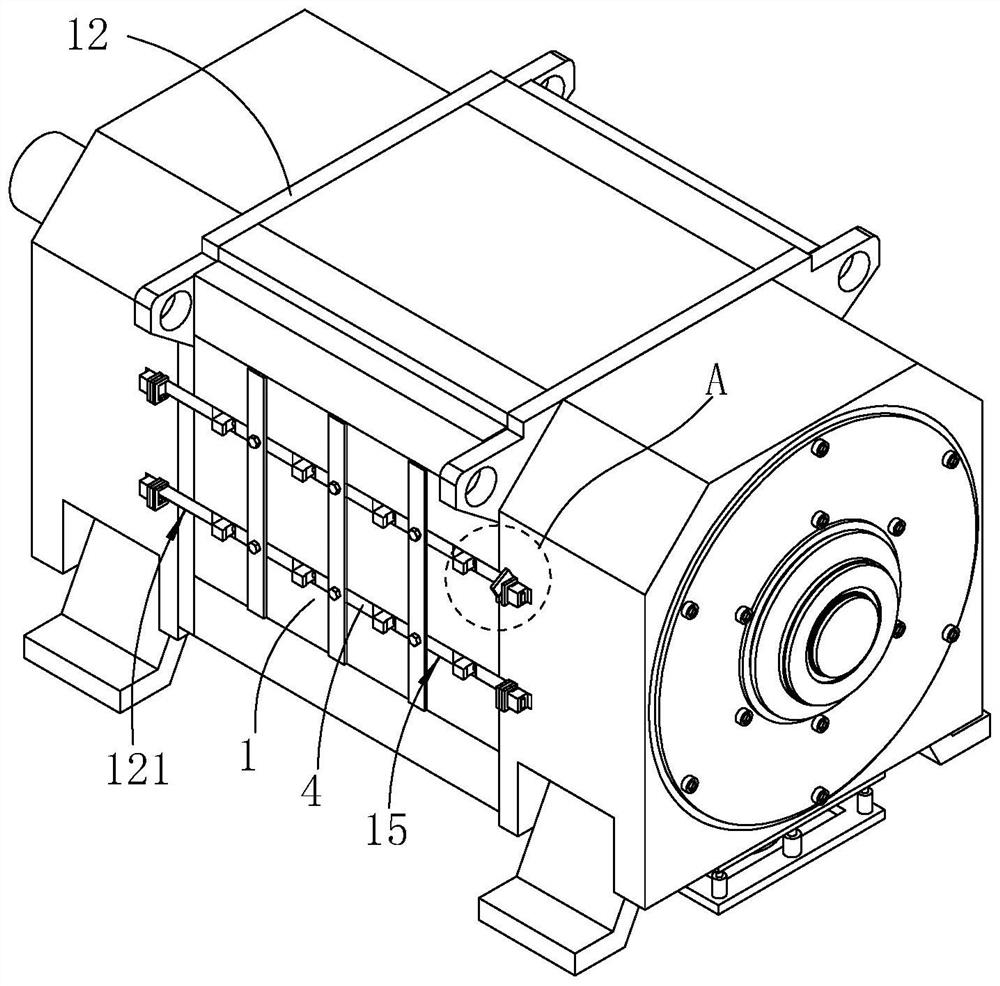
[0050] refer to image 3 and Figure 4 , the difference between this embodiment and embodiment 1 is that

[0051] The side wall of the stator 1 is provided with side slots 15 extending in the axial direction, and each side wall of the stator 1 is arranged with at least two side slots 15, and this embodiment takes two side slots 15 as an example. The side slot 15 is embedded with the side bar 4, and the shapes of the side slot 15 and the side bar 4 projected along the axial direction of the stator 1 are both square.

[0052] Positioning blocks 41 protrude from the side wall of the side bar 4 , and a plurality of annular grooves 42 arranged axially along the stator 1 are provided on the peripheral side wall of the side bar 4 . The side rod 4 is sleeved with a pressure block 43 and a swivel sleeve 44 in the annular groove 42 , wherein the swivel sleeve 44 is threadedly connected with the side rod 4 , and the outer wall of the swivel sleeve 44 does not exceed the annular groove ...


PUM


Abstract

The invention relates to a permanent magnet motor, which comprises a stator, a rotor and an end cover, and is characterized in that the stator comprises a plurality of unit sheets, the plurality of unit sheets are laminated and fixed by welding, the end cover is fixed on the end surface of the stator, the rotor is connected with a rotating shaft, and the rotating shaft is arranged on the end cover. The motor has the advantages that the concentricity error between the stator and the rotor is greatly reduced, the running performance of the motor is improved, and shaking and movement in the rotating process of the rotating shaft are reduced.

Description

technical field [0001] The present application relates to the field of motors, in particular to a permanent magnet motor. Background technique [0002] The motor usually includes a housing, a stator, a rotor, a shaft and an end cover. The stator and the rotor are installed in the housing, and the end covers are fixed at both ends of the housing. During installation, usually the stator is installed into the housing with the inner cavity of the housing as the positioning reference, and then the rotor and the end cover are installed with the housing as the positioning reference. [0003] When the above-mentioned installation method is applied to a small motor, due to structures such as a cage, the positioning accuracy of the stator and the housing can be high, and good concentricity can be maintained. However, when applied to a large motor, due to the large volume and weight of the stator, it is difficult for ordinary cages to provide support and positioning. Therefore, the ou...

Claims


Application Information

Patent Timeline
IPC IPC(8): H02K1/12H02K1/18H02K5/04H02K5/16H02K21/14
CPCH02K1/12H02K1/18H02K5/04H02K5/165H02K21/14
Inventor 贾荣生申发王瑞强魏计升
Owner HANGZHOU NEW HENGLI ELECTRONICS MACHINE MFG
Why Eureka
Try Eureka