Integrated circuit option setting circuit

An integrated circuit and option technology, applied in logic circuits, electrical components, pulse technology, etc., can solve the problems of cost and low efficiency, and achieve the effect of reducing manufacturing costs and saving pin resources

Pending Publication Date: 2022-03-01
岱昆半导体(上海)有限公司
View PDF0 Cites 1 Cited by
  • Summary
  • Abstract
  • Description
  • Claims
  • Application Information

AI Technical Summary

Problems solved by technology

[0004] The option setting method of the above-mentioned prior art is inefficient, and more than two pin resources are required when setting more than two options
In the case of tight pin resources, more costs need to be paid

Method used


Image

  • Integrated circuit option setting circuit
  • Integrated circuit option setting circuit
  • Integrated circuit option setting circuit

Examples


Embodiment 1

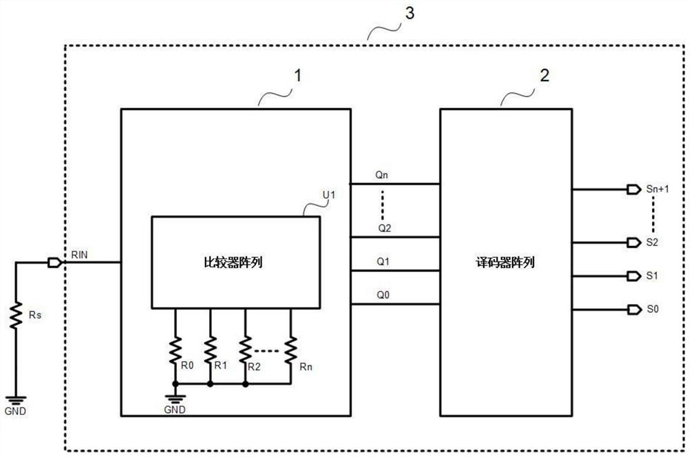
[0025] Such as figure 1 As shown, an integrated circuit option setting circuit includes an integrated circuit 3, a peripheral resistor Rs, and a comparator module 1 and a decoder module 2 are set in the integrated circuit 3;

[0026] Comparator module 1, including comparator array U1 and resistor arrays R0~Rn; where n≥1, and Rn>Rn-1>...>R2>R1>R0, one end of resistor array R0~Rn and comparator array U1 is connected, and the other end is connected to GND;

[0027] The pin RIN of the integrated circuit 1 is the input terminal of the comparator module 1, and Q0~Qn are the output terminals of the comparator module 1; The resistance value of the resistor array R0~Rn:

[0028] When Rs

[0029] When R0

[0030] When R1

[0031] ...

[0032] When Rn-1

[0033] When Rs>Rn, Q0~Qn output state n+1

[0034] The decoder module 2 includes a decoder array, the input terminals...

Embodiment 2

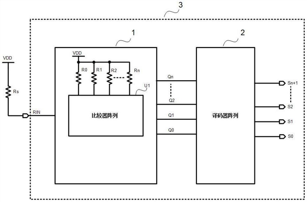
[0037] Such as figure 2 As shown, an integrated circuit option setting circuit includes an integrated circuit 3, a peripheral resistor Rs, and a comparator module 1 and a decoder module 2 are set in the integrated circuit 3;

[0038] Comparator module 1, including comparator array U1 and resistor arrays R0~Rn; where n≥1, and Rn>Rn-1>...>R2>R1>R0, one end of resistor array R0~Rn and comparator array U1 is connected, and the other end is connected to the power supply VDD;

[0039] The pin RIN of the integrated circuit 1 is the input terminal of the comparator module 1, and Q0~Qn are the output terminals of the comparator module 1; The resistance value of the resistor array R0~Rn:

[0040] When Rs

[0041] When R0

[0042] When R1

[0043] ...

[0044] When Rn-1

[0045] When Rs>Rn, Q0~Qn output state n+1

[0046] The decoder module 2 includes a decoder array, th...

Embodiment 3

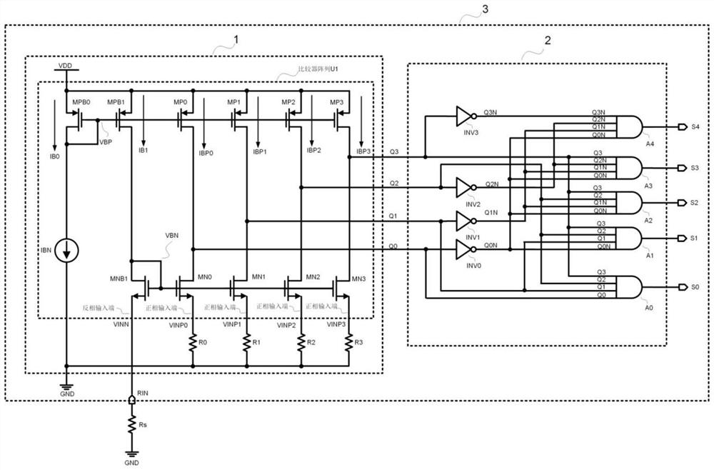
[0049] Such as image 3 Shown is a specific circuit for setting 5 options by setting the impedance of a single pin to ground.

[0050] Among them, the comparator module 1 is composed of a comparator array and a resistor array R0, R1, R2, R3, and the comparator array includes a current source IBN, a P-type MOS transistor MPB0, MPB1, MP0, MP1, MP2, MP3, and an N-type MOS transistor MNB1, MN0, MN1, MN2, MN3;

[0051] One end of the current source IBN is connected to the ground GND, the other end is connected to the drain and gate VPB of the MOS transistor MPB0, and the drain and the gate of the MOS transistor MPB0 are short-circuited;

[0052]The sources of the MOS transistors MPB0, MPB1, MP0, MP1, MP2, and MP3 are connected to the power supply VDD, and the gates of the MOS transistors MPB1, MP0, MP1, MP2, and MP3 are connected to the gate VPB of MPB0;

[0053] The drain of the MOS transistor MNB1 is short-circuited to the gate VBN, the drain of the MOS transistor MNB1, the gat...


PUM


Abstract

An integrated circuit option setting circuit comprises an integrated circuit and a peripheral resistor Rs, and a comparator module and a decoder module are arranged in the integrated circuit. The comparator module comprises a comparator array U1 and resistor arrays R0-Rn; one ends of the resistor arrays R0-Rn are connected with the comparator array U1, and the other ends of the resistor arrays R0-Rn are connected with the ground GND or a power supply VDD; a pin RIN of the integrated circuit is an input end of the comparator module, and Q0-Qn are output ends of the comparator module; the decoder module comprises a decoder array, the input end of the decoder array is connected to Q0-Qn, and the port S0-Sn + 1 is the output end of the decoder module; one end of the external resistor Rs is connected with the input end RIN of the comparator module, and the other end of the external resistor Rs is connected with the ground GND or a power supply VDD; and corresponding circuit options are set by selecting different resistance values of the external resistor Rs. Compared with the prior art, the method has the beneficial effects that more than two options can be set through one pin of the integrated circuit, so that the pin resources of the integrated circuit are greatly saved, and the manufacturing cost is reduced.

Description

technical field [0001] The invention belongs to the technical field of integrated circuit manufacturing, and in particular relates to a circuit for setting integrated circuit options through integrated circuit pins. Background technique [0002] In order to adapt to a wider range of applications, integrated circuits often set the parameters, working modes, and working states of the integrated circuit through pins. For example, two parameter options can be set by connecting one pin to high level or low level, or four parameter options can be set by connecting two pins to high level or low level, as shown in Table 1, through 2 There are 4 options for each pin setting. [0003] pin 1 connected to high level connected to high level connected to low level connected to low level pin 2 connected to high level connected to low level connected to high level connected to low level options 1 2 3 4 [0004] The above-mentioned option setting ...

Claims


Application Information

Patent Timeline
Patent Type & Authority Applications(China)
IPC IPC(8): H03K19/094
CPCH03K19/094
Inventor 肖安全
Owner 岱昆半导体(上海)有限公司
Why Eureka
Try Eureka