
Multifunctional infrared electric energy meter and detection method thereof

A multi-functional technology for electric energy meters, applied in the field of multi-functional infrared electric energy meters and their detection, can solve the problems of high hardware cost, labor cost and time cost, it is difficult to achieve IP54 protection level, and there are many wirings when inspecting electric energy meters. Achieve the effect of improving factory quality, improving antistatic level and reducing production cost

Pending Publication Date: 2019-04-02
ZHANGZHOU CANNET ELECTRICAL APPLIANCE
View PDF0 Cites 0 Cited by
  • Summary
  • Abstract
  • Description
  • Claims
  • Application Information

AI Technical Summary

Problems solved by technology

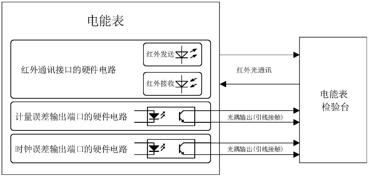
For common methods of testing electric energy meters, see figure 1 , use infrared interface for communication, use an optocoupler contact type to output metering error signal, and use an optocoupler contact type to output clock error signal, the circuit hardware is complex, there are many interfaces, it is difficult to achieve the protection level of IP54; when checking the electric energy meter There are many wirings and cumbersome detection steps; the hardware cost, labor cost and time cost are high, which is not conducive to production automation and low production efficiency

Method used


Image

  • Multifunctional infrared electric energy meter and detection method thereof
  • Multifunctional infrared electric energy meter and detection method thereof
  • Multifunctional infrared electric energy meter and detection method thereof

Examples


Embodiment Construction

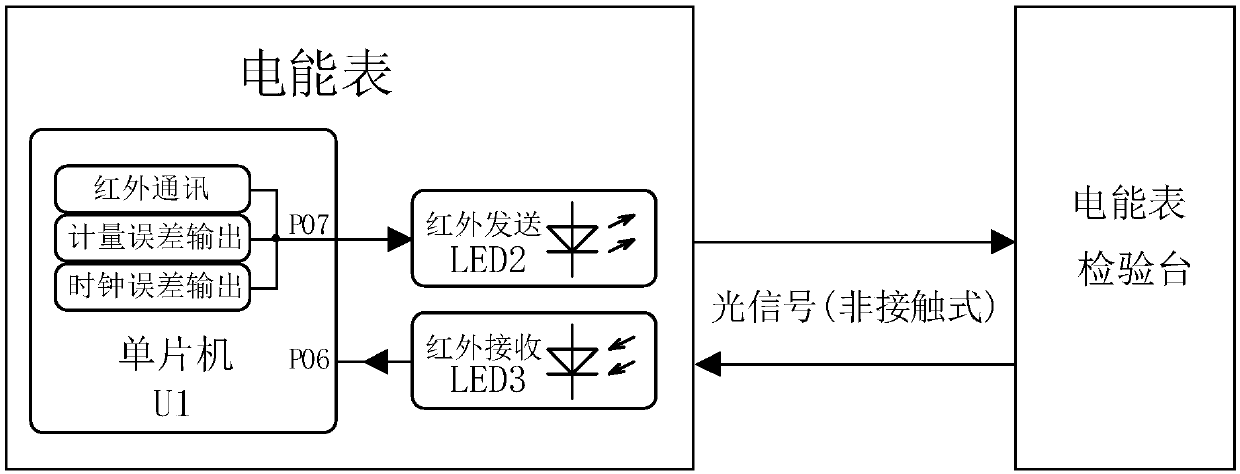
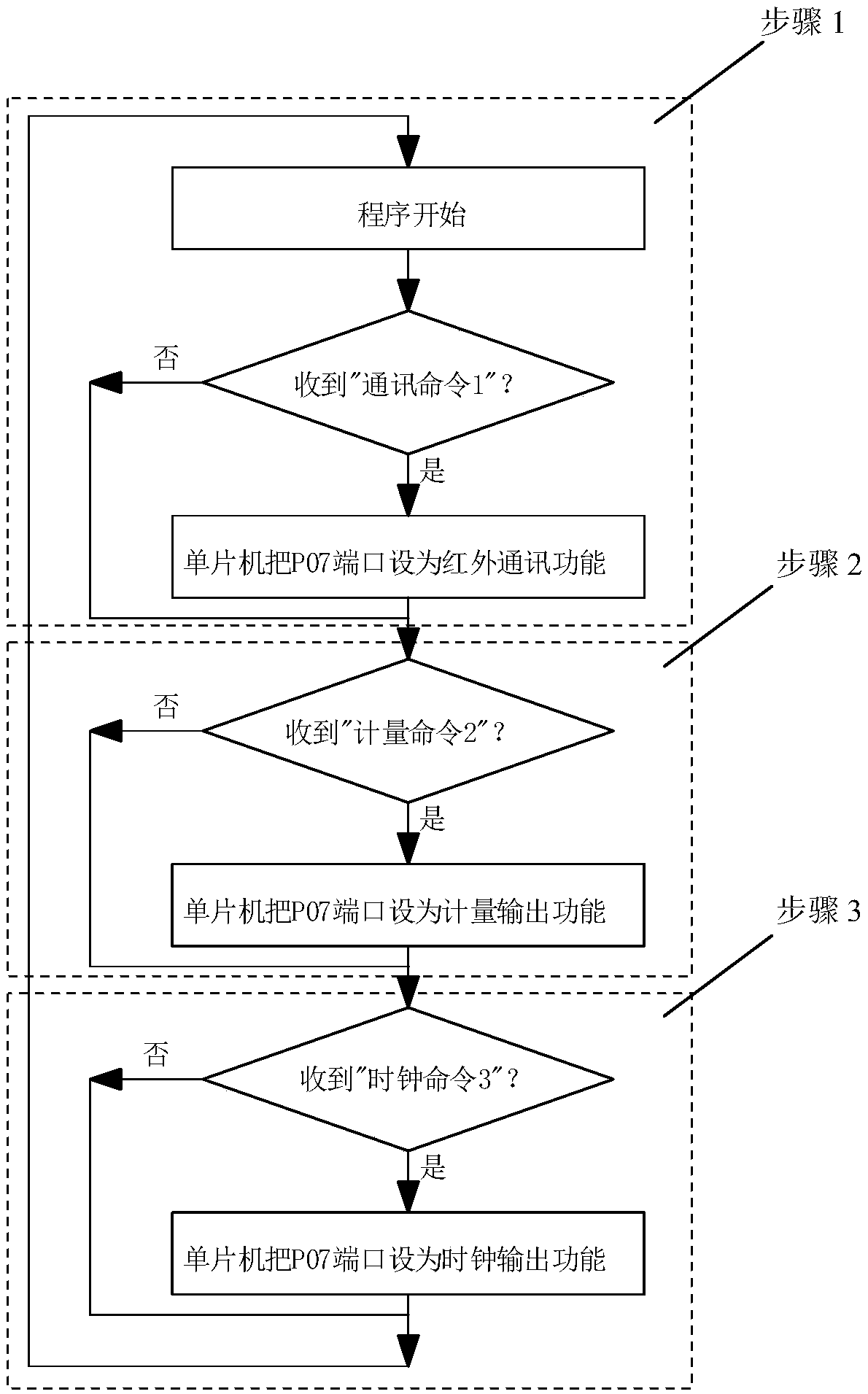
[0019] Examples, see figure 2 and image 3 As shown, a multifunctional infrared electric energy meter of the present invention includes a main control chip single-chip microcomputer U1, an infrared emitting tube LED2 and an infrared receiving tube LED3, and the single-chip microcomputer U1 is connected to the infrared receiving tube to receive the electric energy meter inspection platform through the P06 port The detection instruction includes "communication command 1", "metering command 2" and "clock command 3"; the single-chip microcomputer U1 controls the infrared emission tube LED2 to output different waiting Detection signal, the signal to be detected includes infrared communication signal, measurement error signal and clock error signal; the electric energy meter inspection station detects the electric energy meter according to the signal to be detected output by the infrared emitting tube LED2.

[0020] The detection method of the multi-functional infrared electric en...


PUM


Abstract

The invention discloses a multifunctional infrared electric energy meter. The multifunctional infrared electric energy meter comprises a single chip microcomputer and an infrared transmitting tube andan infrared receiving tube connected to the single chip microcomputer. The single chip microcomputer receives a detection instruction of an external electric energy meter detecting device through theinfrared receiving tube. The detection instruction comprises a communication command, a measurement command, and a clock command. The single chip microcomputer controls the infrared transmitting tubeto output a signal to be detected according to the detecting instruction. The electric energy meter detecting device detects the electric energy meter according to the signal to be detected outputtedby the infrared transmitting tube. The signal to be detected comprises an infrared communication signal, a measurement error signal, and a clock error signal. The multifunctional infrared electric energy meter has advantages that the IP54 waterproof rating of the electric energy meter is realized at a low cost, the antistatic level of the electric energy meter is improved, and the overall productquality is improved; and the production efficiency is improved, the production cost is reduced by a non-contact detection method, the automation level of the electric energy meter production is improved, and the quality of electric energy meter products is improved.

Description

technical field [0001] The invention relates to a multifunctional infrared electric energy meter and a detection method thereof. Background technique [0002] In the production process of the electric energy meter, the electric energy meter needs to be detected by the electric energy meter detection equipment, and various output signals of the electric energy meter received by the detection equipment are output through the hardware circuit of the electric energy meter. For common methods of testing electric energy meters, see figure 1 , use infrared interface for communication, use an optocoupler contact type to output metering error signal, and use an optocoupler contact type to output clock error signal, the circuit hardware is complex, there are many interfaces, it is difficult to achieve the protection level of IP54; when checking the electric energy meter There are many wirings, and the detection steps are cumbersome; the hardware cost, labor cost and time cost are hig...

Claims


Application Information

Patent Timeline
Patent Type & Authority Applications(China)
IPC IPC(8): G01R35/04G01R11/25
CPCG01R11/25G01R35/04
Inventor 骆贵泉郭高霖陈俊毅
Owner ZHANGZHOU CANNET ELECTRICAL APPLIANCE
Learn More