Input structure and electronic equipment
A technology of input structure and operating parts, applied in branch equipment, telephone structure, telephone communication, etc., can solve the problems of poor user experience, many times of use, affecting the appearance of electronic equipment, etc.
Pending Publication Date: 2022-03-01
ONEPLUS TECH SHENZHEN
5 Cites 0 Cited by
AI-Extracted Technical Summary
Problems solved by technology
However, the setting of multiple buttons will occupy a large space in the electronic device, making the structure and installation of the electronic device more complicated, and affecting the appearance of the electronic device
For example, the design of today's mobil...
Method used
[0080] In some specific embodiments, the implementing part 23 is provided with anti-slip lines, so as to facilitate the user to operate and avoid slipping.
[0101] The outer diameter of the elastic positioning assembly 4 is equal to or slightly smaller than the inner diameter of the accommodating chamber 31, thereby guiding the elastic positioning assembly 4 to prevent the elastic positioning assembly 4 from shifting, so as to ensure that the elastic positioning assembly 4 is stable Reliable elastic telescoping action.
[0105] When the operating member 2 slides relative to the middle frame 10, the positioning ball 42 can move from one positioning portion 21 to another adjacent positioning portion 21. In the embodiment, the positioning portion 21 may be a spherical groove, and an arc surface transition may also be selected between two adjacent positioning portions 21 . Therefore, the positioning ball 42 can be smoothly moved from one positioning portion 21 to the adjacent positioning portion 21 , avoiding the jamming problem.
[0111] In some speci...
Abstract
The invention discloses an input structure and electronic equipment, and relates to the technical field of electronic equipment. The input structure comprises a base, an operation piece, an elastic positioning assembly and a detection assembly. The operating piece is movably mounted on one side of the base; the elastic positioning assembly is arranged on the side, away from the operation piece, of the base. The end face, close to the elastic positioning assembly, of the operating piece is provided with at least two positioning parts, and the positioning parts are matched with the elastic positioning assembly to position the operating piece. The detection assembly is used for detecting the position change of the operation piece and generating a corresponding trigger signal. The electronic equipment comprises the input structure. The input structure provided by the invention can meet the multi-function switching of the electronic equipment, and does not occupy a large space.
Application Domain
Telephone set constructions
Technology Topic
EngineeringElectrical and Electronics engineering +2
Image
Examples
- Experimental program(3)
Example Embodiment
[0061] Example one
[0062] An input structure is provided in the mobile phone, tablet, laptop, audio, MP3 player, MP4 player and other portable electronic devices. Wherein, the user can adjust or change the working state, function or mode of the respective electronic device, etc. by operating the input structure. The above is only an example of the input structure application, and it should not be understood to limit the limitations of the present application.
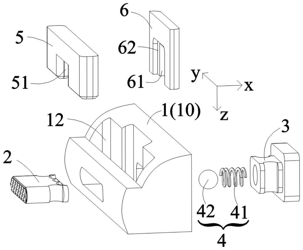
[0063] Such as figure 1 and Figure 12 As shown in, in the embodiment, the input structure includes a base 1, an operating member 2, an elastic positioning assembly 4, and a detection assembly 7. Wherein, the operating member 2 is slid to be mounted on one side of the susceptor 1, and it is understood that the operating member 2 can move to the base 1 to change the position of the operator 2 relative to the base 1.
[0064] The elastic positioning assembly 4 is disposed on the other side of the base 1, and the elastic positioning assembly 4 is disposed opposite the operating member 2. The elastic positioning assembly 4 is used to position the opener 2 to secure the opener 2 to a particular position, avoid moving the operator 2 with respect to the base 1 freely.
[0065] Such as figure 2 and Figure 5 As shown, the operating member 2 is provided with at least two positioning portions 21 adjacent to the end of the elastic positioning assembly 4; wherein the positioning portion 21 can be in the groove shape, and one end of the elastic positioning assembly 4 can be located in the positioning portion 21. When the elastic positioning assembly 4 is coupled to the partition portion 21, the positioning of the operation member 2 can be realized.
[0066] In some specific embodiments, the positioning portion 21 can be arranged in any line direction on the Y-Z plane; corresponding, the operation member 2 is disposed along the straight line in the sliding direction of the base 1. On the Y-Z plane, the resilient positioning assembly 4 remains unchanged with respect to the position of the base 1. When the operating member 2 is slidked relative to the susceptor 1, the elastic positioning assembly 4 can switch from a bit portion 21 to another adjacent positioning portion 21, and achieve positioning of the operation member 2.
[0067] In an embodiment, the detecting assembly 7 is used to detect the positional change of the operation member 2 and generate a corresponding trigger signal. It will be appreciated that the detecting assembly 7 can produce different trigger signals when the operator 2 is in different positions.
[0068] In use, the detection assembly 7 can be connected to the main control unit of the electronic device, which can be implemented by wired, wireless communication, etc., thereby sending the trigger signal to the master unit. The user can push the opener 2 to slide so that the overall of the operation member 2 changes with respect to the position of the base 1; wherein the detecting assembly 7 can generate a corresponding trigger signal to the main control unit according to the detected position change information. The control unit can control the switching of the electronic device according to the received trigger signal to perform the corresponding operating state, mode, or function.
[0069] In some specific embodiments, the positioning portion 21 can be set to two, three, four or more, depending on the need to be electronically devices, and specifically.
[0070] In other embodiments, the operating member 2 is rotatably mounted on the base 1 side, and the rotating shaft may be the central axis of the operating member 2. Accordingly, on the Y-Z plane, the positioning portion 21 surrounds the central axis of the operating member 2 in an annular arrangement. The elastic positioning assembly 4 is equipped with the edge setting of the operating member 2, and is set to the positioning portion 21. In use, the user rotates the operator 2, so that the respective portions in the operation member 2 perform a change in the circumferential direction relative to the susceptor 1, and the elastic positioning assembly 4 can switch positioning in the positioning portion 21. At the same time, the detecting assembly 7 can detect the positional change of the portion of the operation member 2 to generate a corresponding trigger signal.
[0071] In other embodiments, the operating member 2 is rotatably mounted on the base 1, and the rotation shaft is disposed at the eccentric position of the operating member 2. Correspondingly, the plurality of positioning units 21 are disposed on one end surface of the operating member 2 near the elastic positioning assembly 4, and the plurality of positioning portions 21 are annularly arranged. The elastic positioning assembly 4 is equipped with the edge setting of the operating member 2, and is set to the positioning portion 21. In use, the user turns the opener 2 to change the operating member 2 relative to the susceptor 1, and the elastic positioning assembly 4 can switch positioning in the positioning portion 21. At the same time, the detection assembly 7 can detect the positional change of the operating member 2 to generate a corresponding trigger signal.
[0072] From this, it can be seen that when the electronic device has a variety of functions, modes or operational states, the corresponding number of positioning units 21 can be set on the operating member 2, which can meet multi-function switching, multi-mode switching, or multi-operating state switching, etc. The need, there is no need to set a large number of buttons, thereby reducing the occupancy of the internal space of the electronic device, simplifies the internal structure, and avoids the impact on the external form of the electronic device. At the same time, the configuration of the input structure of this application is relatively simple, shorted, convenient in assembly, low cost, and high reliability.
Example Embodiment
[0073] Example 2
[0074] An input structure is provided in an embodiment, which can be applied to a mobile phone;
[0075] In an embodiment, the input structure is disposed on the side of the mobile phone, and the base 1 can be part of the middle frame 10. Hereinafter, a detailed description is taken as an example in performing up and down along the Y-axis direction.
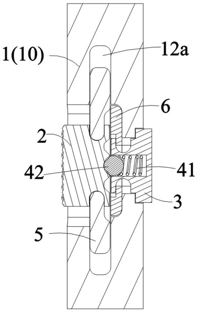
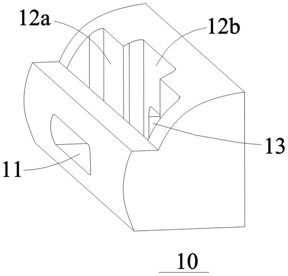
[0076] Such as figure 1 and figure 2 As shown, the middle frame 10 is provided with an assembly space 12, and at least one side in both sides of the assembly space 12 communicates with the outside. In this embodiment, the rear side of the assembly space 12 is in communication with the outside world. Specifically, such as figure 2 As shown, it can be connected to the outside near the side of the paper.
[0077] Such as Figures 2 to 4 As shown, the first mounting hole 11 is provided on one side of the middle frame 10, and one end of the first mounting hole 11 is in communication with the assembly space 12, and the other end is in communication with the outside environment. The first mounting hole 11 may be a long-shaped passage that extends in the height direction of the block 10. The operation member 2 is provided with one end of the positioning portion 21 extends into the assembly space 12 after passing through the first mounting hole 11, and the operating member 2 can be pulled up and down relative to the first mounting hole 11.
[0078] In an embodiment, the assembly space 12 includes a communication-set first lumen 12a and a second restricted chamber 12b. In the width direction of the input structure, the first limiting chamber 12a is disposed adjacent to the operator 2 compared to the second limiting chamber 12b. The positioning portion 21 of the operation member 2 is located within the first limiting chamber 12a.
[0079] Such as figure 2 and Figure 5 As shown, the operation member 2 also includes an execution unit 23, and the execution unit 23 is disposed at one end of the operating member 2 away from the positioning portion 21. The execution unit 23 is located outside of the middle frame 10, i.e., the execution unit 23 is disposed away from the first mounting hole 11 away from the side of the assembly space 12, which is exposed to the outside, thereby facilitating the user touching the implementation unit 23 for related operations. In use, the user can push the opener 2 by the operation of the execution unit 23 to perform up and down.
[0080] In some specific embodiments, the execution unit 23 is provided with a projection, thereby facilitating the user to operate, avoiding slipping.
[0081] Such as figure 1 , Figures 2 to 6 As shown, the input structure further includes a first locking member 5, and the first locking member 5 is joined in the first limiting chamber 12a. At the same time, the first locking member 5 is inserted with the operating member 2, thereby positioning one end of the opener 2 in the middle frame 10 to achieve the assembly of the operating member 2.
[0082] Specifically, the operating member 2 is provided with one end of the positioning portion 21, and the two first insertion portions 22 are separated from the upper and lower sides of the operating member 2, and the two first inserts 22 can be Symmetrical setting.
[0083] The first locking member 5 is in a U-shaped structure. The inner wall of the first lock 5 is provided with two opposing second starting portions 51, and the two second bonding portions 51 are symmetric. The two second starting portions 51 are set to one or one of the two first insertions 22. When the first locking member 5 is coupled to the operating member 2, the second starting portion 51 is coupled to the first insertion portion 22.
[0084] In some specific embodiments, the first insertion portion 22 is grooved; corresponding, the second start 51 presents a matched convex. When the first insertion portion 22 is connected to the second start 51, the second starting portion 51 is fitted in the first insertion portion 22.
[0085] In other embodiments, the first insertion portion 22 is raised; corresponding, the second start 51 presents a groove shape. When the first insertion portion 22 is coupled to the second start portion 51, the first starting portion 22 is fitted in the second bonding portion 51.
[0086] Such as figure 2As shown, the width of the first locking member 5 is equal to the width of the first restricted chamber 12a, thereby limiting the first locking member 5 in the first restricted cavity 12a in the width direction, thereby avoiding the user. The execution unit 23 of the operation member 2 cannot be hit. The height of the first locking member 5 is smaller than the height of the first limiting chamber 12a, so that the first locking member 5 can be pulled up and down within the first limiting chamber 12a. At the same time, the cross section of the first locking member 5 is larger than the cross section of the first mounting hole 11 to limit the first locking member 5 in the first limiting chamber 12a, and thereby providing the operating member 2 with the positioning portion 21. One end is limited in the first limiting chamber 12a. The cross section of the first locking member 5 and the cross section of the first mounting hole 11 are intercepted along the Y-Z plane.
[0087] The height of the operating member 2 is smaller than the height of the first mounting hole 11, and the thickness of the operating member 2 can be equal to the thickness of the first mounting hole 11. At the same time, the first locking member 5 can be equal to the active stroke of the operation member 2 within the first mounting hole 11.
[0088] When assembled, the opener 2 is provided with the one end of the positioning portion 21 extends through the first mounting hole 11 into the first cell cavity 12a. Subsequently, the first locking member 5 is inserted from the side of the assembly space 12 and the outside of the outside; the second start portion 51 on the first locking member 5 is corresponding to the first insertion portion 22 on the operating member 2. The first locking member 5 is inserted with the operating member 2. Thereby, it is possible to assemble the opener 2 to the middle frame 10, so that the assembly is extremely convenient.
[0089] Further, such as Figures 2 to 4 As shown, the elastic positioning assembly 4 is mounted on one side of the middle frame 10 via a mount 3. Specifically, the middle frame 10 is provided with a second mounting hole 13 from one side of the first mounting hole 11, and the second mounting hole 13 is in communication with the second limiting chamber 12b. The fixing seat 3 is mounted at the second mounting hole 13, and one end of the fixing seat 3 extends into the second restricted chamber 12b; the elastic positioning assembly 4 is attached to the second end of the second resident chamber 12b.
[0090] In some embodiments, the fastener 3 is attached to the second locking member 6 in the second restricted chamber 12b by the second locking member 6, so that the fastener 3 is mounted on the middle frame 10.
[0091] Such as figure 2 and Figure 4 As shown, the second mounting hole 13 is a step hole, and the second mounting hole 13 includes a relantable first through hole portion 13a and the second through hole portion 13b. The second through hole portion 13b is disposed adjacent to the second lumen 12b, and the cross section of the second through hole portion 13b is smaller than the cross section of the first through hole portion 13a, thereby at the first through hole portion 13a and the second through hole portion. The 13b connection forms a first abutting portion 13c, and the first abutting portion 13c is used for a limiting member 3. Among them, the cross section of the first through hole portion 13a and the cross section of the second through hole portion 13b are taken along the Y-Z plane.
[0092] Such as figure 2 and Figure 7 As shown, the fixing seat 3 is disposed on one side of the second restricted chamber 12b, and the second abutting portion 33 is abutting with the first abutment portion 13c, thereby performing the fixing seat 3 in the width direction. One direction limit. The second locking member 6 is inserted in the second restricted chamber 12b, and the second locking member 6 is coupled to the fixed seat 3 to perform a limit of the fixed seat 3 in the width direction. Thereby, the fixing seat 3 is fixed to the middle frame 10.
[0093] Such as figure 2 , Figure 7 and Figure 8 As shown, the fastener 3 is disposed adjacent to one end of the second restricted chamber 12b, and the two third bonding portions 32 are separated from the upper and lower sides of the fixed seat 3, and the two third junctions. The portion 32 can be symmetric.
[0094] In some specific embodiments, the second locking member 6 also has a U-shaped structure. A fourth-pin portion 61 is provided on the two inner walls of the second locking member 6, and the two fourth joining portions 61 can be configured; the two fourth-fitting portions 61 correspond to the two passage 32 set up. When the second locking member 6 is joined to the fixed seat 3, the two fourth joining portions 61 are coupled to the third joining portion 32 of the corresponding side.
[0095] In some specific embodiments, the third bonding portion 32 is grooved; corresponding, the fourth start portion 61 is raised. When the third joining portion 32 is coupled to the fourth joining portion 61, the fourth start portion 61 is fitted in the third joining portion 32.
[0096] In still other embodiments, the third joining portion 32 is raised; corresponding, the fourth-opening portion 61 presents a groove shape. When the third joining portion 32 is coupled to the fourth joining portion 61, the third joining portion 32 is fitted in the fourth joining portion 61.
[0097] Such as figure 2 and Figure 8 As shown, the height of the second locking member 6 is equal to the height of the second restricted chamber 12b, and the second locking member 6 is set to the first locking member 5, thereby avoiding the second locking member 6 in the second Limit cavity 12b activity. The cross section of the second locking member 6 is larger than the cross section of the second mounting hole 13 adjacent to the second restricted chamber 12b, thereby limiting the second locking member 6 in the second restricted cavity 12b, thereby ensuring the holder One end of 3 is located in the second restricted chamber 12b. The second locking member 6 is disposed on one side of the second restricted chamber 12b with a limit slot 62 for embedding the fastener 3, thereby avoiding the end of the fastener 3 to interfere with the operating member 2 and the first lock. Pieces 5 slide. The cross section of the second locking member 6 and the cross section of the second mounting hole 13 are taken along the Y-Z plane.
[0098] At the time of installation, the one end of the fixing seat 3 passes through the second mounting hole 13 into the second restricted hole 12b, and the second abutting portion 33 is contrary to the first abutment portion 13c. Subsequently, the second locking member 6 is inserted from one side of the assembly space 12 opening, and the fourth interconnect portion 61 is inserted with the third joining portion 32, and the second locking member 6 is inserted with the fixed seat 3. . At the same time, the end portion of the fixed seat 3 is located adjacent the second restricted chamber 12b is limited in the limit slot 62. Thereby, the fixing seat 3 is fixed to the middle frame 10 is implemented.
[0099] Such as figure 1 , figure 2 and Figure 7 As shown, the inside of the fixing seat 3 is provided with a receiving chamber 31, and the accommodating chamber 31 is in communication with the assembly space 12. The resilient positioning assembly 4 is limited in the accommodating chamber 31, and one end of the elastic positioning assembly 4 protrudes in the accommodating chamber 31 and extends into the assembly space 12 to facilitate the resilient positioning assembly 4 to contact the positioning portion 21.
[0100] In some specific embodiments, the elastic positioning assembly 4 includes an elastic member 41 and a positioning ball 42, an elastic member 41 is embedded in the accommodating chamber 31; at least a portion of the positioning ball 42 is located in the accommodating chamber 31, thereby avoiding positioning ball 42 detaching Fixed seat 3; At the same time, the positioning ball 42 has a portion of the positioning of the accommodating chamber 31 to facilitate the positioning ball 42 to contact the positioning portion 21. One end of the elastic member 41 is abutment with the bottom of the accommodating chamber 31, that is, the accommodating chamber 31 is away from one end of the second lumen 12b. The other end of the elastic member 41 is contrast with the positioning ball 42; the elastic member 41 is compressed between the positioning ball 42 and the receiving chamber 31, so that the elastic member 41 pushes the positioning ball 42 to move in the direction of the positioning portion 21.
[0101] The outer diameter of the elastic positioning assembly 4 is equal to or slightly smaller than the inner diameter of the accommodating chamber 31, so that the elastic positioning assembly 4 can be oriented, avoiding the elastic positioning assembly 4 to ensure that the elastic positioning assembly 4 performs stable and reliable elasticity. Telescopic action.
[0102] In some embodiments, the elastic member 41 can be combined with one or more of the resilient components such as spring, flexible block, and shrapnel.
[0103] In some embodiments, the positioning ball 42 can be one of the balls such as balls, elastic balls. Of course, the positioning ball 42 is also a solid ball or hollow ball.
[0104] In still other embodiments, the elastic positioning assembly 4 can also include a sleeve (not shown in the drawing), the elastic member 41 and the positioning ball 42 are mounted in the sleeve, thereby forming a complete bunning pin structure for the elastic positioning assembly 4 To facilitate overall installation. The sleeve can be fixed to the accommodating chamber 31; specifically, between the sleeve and the accommodating chamber 31 can be connected by a threaded connection, an overference fit, and the like.
[0105] When the opener 2 is slid, the positioning ball 42 can be moved from a bit portion 21 to another adjacent positioning portion 21. In an embodiment, the positioning portion 21 can be selected from a spherical groove, and an arc transition can also be selected between adjacent two positioning portions 21. Thereby, the positioning ball 42 can be smoothly moved from a certain bit portion 21 to the adjacent positioning portion 21 to avoid a problem of station.
[0106] Such as Figure 9 and Figure 12 As shown, the detection assembly 7 includes a signal generating member 71 and a trigger member 72, and the trigger 72 is used to trigger the signal generating 71 to generate a corresponding trigger signal. Wherein, the signaling member 71 is fixed to the middle frame 10; the trigger 72 is moved synchronously with the operating member 2. Thus, when the operation member 2 is slid relative to the middle frame 10, the trigger 72 can be synchronously moved relative to the signal generating member 71.
[0107] In some embodiments, the signal generating member 71 can be secured to the main board 8 of the phone and connected to the main control unit on the main board 8; the signal generating member 71 is arranged close to the input structure, so that the trigger 72 generates the signal generating member 71. effect.
[0108] Of course, in some other embodiments, the signal generating member 71 can also be provided directly on the block 10.
[0109] In some embodiments, the trigger 72 can be secured to one end portion of the first locking member 5 such that the trigger 72 can be moved synchronously with the operator 2. The trigger 72 is disposed at one end portion of the first locking member 5 near the signaling member 71.
[0110] In other embodiments, the trigger 72 can also be directly disposed on one end of the operating member 2 close to the fastener 3.
[0111] In some specific embodiments, the trigger 72 can be a magnet; corresponding, the signaling member 71 can be a Hall sensor. When the trigger member 72 is moved relative to the signal generating member 71, the magnetic field around the signal generating member 71 changes, thereby changing the magnetic flux detected by the signal generating member 71, and the signal generating member 71 generates the corresponding trigger signal and transmits it. The main control unit. In the embodiment, two signaling occiral 71 can be provided in the moving direction of the trigger 72, and the two signaling assembly 71 work together, thereby improving the detection accuracy and sensitivity.
[0112] Of course, in some other embodiments, the number of signal generating members 71 can also be set to one, three, four or more other numbers as needed, and do not limit this.
[0113] Such as Figure 10 As shown in some other embodiments, the signal generating 71 can also be used for distance sensors. Correspondingly, the trigger 72 can include a plurality of different depths of sink, the groove bottom of the sink and the signal generating member 71 are disposed opposite. Wherein, the number of sinks is equal to the number of positioning portions 21, and the sink is set corresponding to the positioning portion 21. When the elastic positioning assembly 4 abuts the positioning portion 21, a sinking groove corresponds to the signal generating member 71. Thereby, the moving position of the movable portion 2 can be determined by the signal generating member 71 to determine the moving position of the operation member 2, and thereby generate a respective trigger signal by the signal generating member 71.
[0114] Such as Figure 12 and Figure 13As shown in, in use, the user moves by pushing the operating member 2, so that the opener 2 is in different locations. In this process, the operating member 2 extruded the elastic positioning assembly 4, in the width direction of the input structure, so that the elastic positioning assembly 4 has a round-trip moving stroke, so that the elastic positioning assembly 4 is moved from the azal portion 21 to another. The bit portion 21 is in the position 21. At the same time, the trigger 72 also occurs relative to the signal generating member 71, so that the signal detected by the signal generating member 71 changes, thereby generating the signal generating member 71 to generate the corresponding trigger signal to the main control unit, and then the main control unit Control mobile phone switching corresponding functions, working mode, etc.
[0115] When the user moves the opener 2, since the elastic force needs to overcome the elastic member 41, it can increase the user's operating hand, and it is convenient for the user to identify the operation action.
[0116] Wherein, the elastic positioning assembly 4 can be positioned to the opener 2, and can be maintained in the same position without being an external force. At the same time, the signal generating member 71 can also be made to a stable trigger signal to the main control unit, so that the mobile phone can maintain the reliability of the input structure in the respective mode of operation, function, or state.
[0117] In some specific embodiments, three positioning portions 21 are provided on the operating member 2, including the first positioning portion 21a, the second positioning portion 21b, and the third positioning portion 21c, thereby forming a three-segment input structure. The first positioning portion 21a, the second positioning portion 21b, and the third positioning portion 21c are arranged in sequence from the top to bottom. The first positioning portion 21a, the second positioning portion 21b, and the third positioning portion 21c may correspond to the mute mode, vibration mode, and ring mode in the mobile phone reminder mode. In use, the user passes through the moving member 2 to abut the elastic positioning assembly 4 in different positioning unit 21, thereby fixing the operating member 2 at a respective position. The detection assembly 7 issues a corresponding trigger signal to the master unit according to the position of the operating member 2, and then controls the mobile phone to the silent mode, vibration mode, or ring mode by the master unit.
[0118] In some specific embodiments, the first positioning portion 21a corresponds to the silent mode, the second positioning portion 21b corresponds to the vibration mode, and the third positioning portion 21c corresponds to the ring mode.
[0119] Exemplary, the initial state of the input structure is a ring mode, corresponding, the elastic positioning assembly 4 abuts in the third positioning portion 21c. When the reminder mode needs to be adjusted is the vibration mode, the opener 2 can be pushed upward relative to the middle frame 10; during which the opener 2 is pressed, the elastic positioning assembly 4 can be embedded in the fixing seat 3. When the second positioning portion 21b corresponds to the elastic positioning assembly 4, the elastic positioning assembly 4 resets against the second positioning portion 21b. At this time, the detection assembly 7 detects the position change of the operation member 2, and issues a corresponding trigger signal to the main control unit of the mobile phone, and the main control unit controls the phone to switch to the vibration mode according to the received trigger signal.
[0120] In other embodiments, the input structure can also be used for switching of functional modes such as mobile phone screen brightness adjustment, volume adjustment, and is not limited thereto.
[0121] In some specific embodiments, in the assembly, the operating member 2 can be provided with one end of the positioning portion 21 insertion block 12, and then the first locking member 5 is inserted into the assembly space 12, and at the same time, The first locking member 2 is coupled to the operating member 2 to provide an end of the operating member 2 with a positioning portion 21 in the middle frame 10. Subsequently, the elastic positioning assembly 4 can be mounted in the fixed seat 3, and then the fixing seat 3 is provided with one end of the elastic positioning assembly 4 insertion box 10; insert the second lock 6, so that the second lock The stop 6 is inserted with the fixed seat 3 to complete the assembly of the input structure.
[0122] In still other embodiments, the fixing seat 3 and the second locking member 6 assembled with the elastic positioning assembly 4 can also be fitted into block 10, and then assemble the opener 2 and the first lock 5. Box 10.
[0123] In summary, the input structure of this application is simple, suitable for assembly, short size chain, low cost, and high reliability. At the same time, the switching of different numbers of functionality, modes or operation, or the like can be satisfied by setting different numbers of positioning units 21, without setting a more complex button structure, thereby also improving the user's experience.
Example Embodiment
[0124] Example three
[0125] Such as Figure 11 to 13 As shown, the present application provides an electronic device, including an input structure provided in Embodiment 1 or Embodiment 2.
[0126] In an embodiment, the electronic device can be a mobile phone.
[0127] In other embodiments, the electronic device can also be a tablet, a laptop, an audio, an MP3 player, an MP4 player, and other devices.
[0128] The base 1 is part of the frame 10 in the electronic device, and the execution unit 23 of the operation member 2 is located outside the electronic device, thereby facilitating the user to perform related operations. The signaling assembly 71 in the detection assembly 7 can be directly provided on the main board 8 of the electronic device, and the signal generating member 71 is electrically connected to the main control unit of the electronic device.
[0129] In use, the user can switch the operating status, mode, or function of the electronic device through the operating member 2.
PUM


Description & Claims & Application Information
We can also present the details of the Description, Claims and Application information to help users get a comprehensive understanding of the technical details of the patent, such as background art, summary of invention, brief description of drawings, description of embodiments, and other original content. On the other hand, users can also determine the specific scope of protection of the technology through the list of claims; as well as understand the changes in the life cycle of the technology with the presentation of the patent timeline. Login to view more.