Electric curtain control device

A technology for control devices and electric curtains, which is applied to window decorations, applications, home appliances, etc., can solve the problems of easy cross-influence, poor user experience, and poor product stability during pressing operations, so as to avoid poor product stability. , Simple structure, low cost effect

Active Publication Date: 2022-03-04
ULTIMATE IOT (SHANGHAI) TECH LTD +1
View PDF10 Cites 1 Cited by
  • Summary
  • Abstract
  • Description
  • Claims
  • Application Information

AI Technical Summary

Problems solved by technology

[0006] The purpose of the present invention is to provide an electric curtain control device to solve the problem that the control button in the prior art not only controls the rotation of the driven wheel to realize assembly and disassembly, but also controls the conduction of the circuit, which leads to cross-effects easily during pressing operations and product stability. Technical problems of poor performance and poor user experience

Method used


Image

  • Electric curtain control device
  • Electric curtain control device
  • Electric curtain control device

Examples


specific Embodiment 1

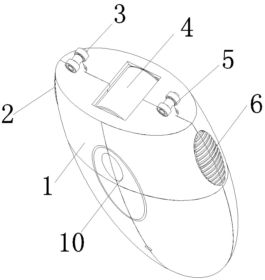
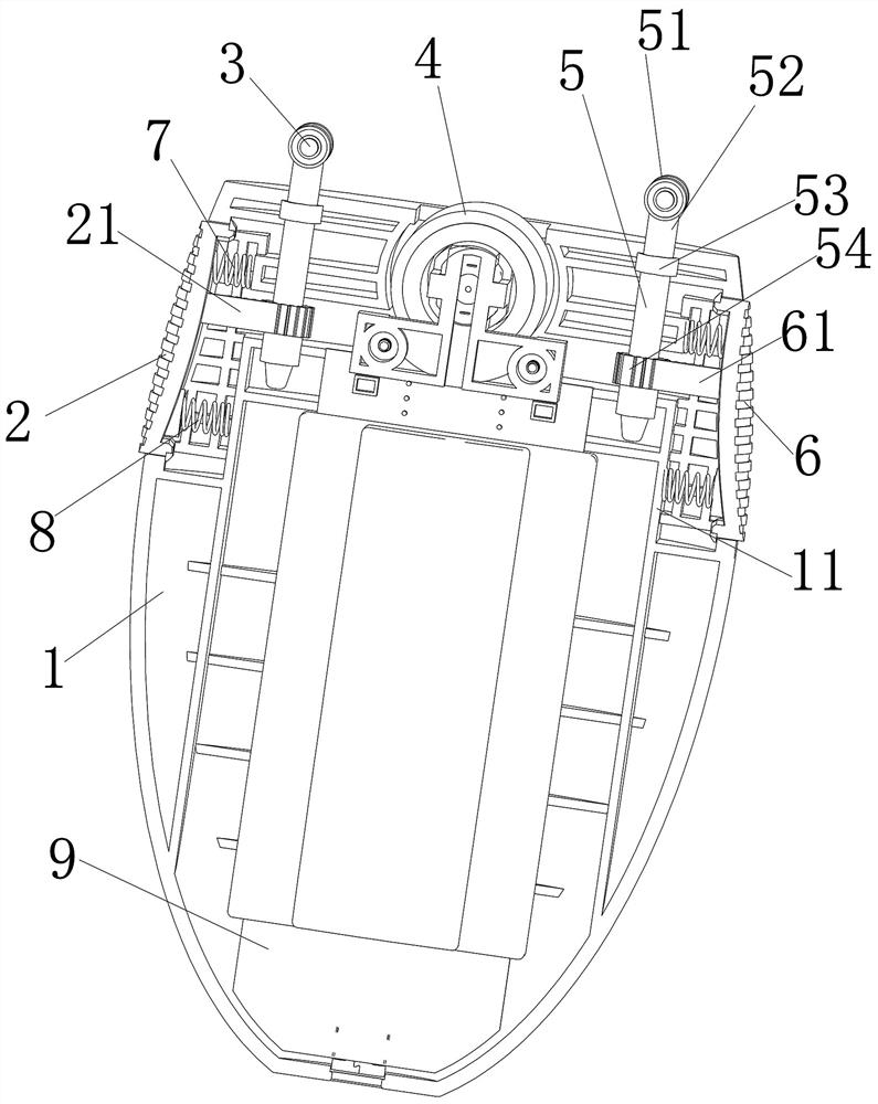
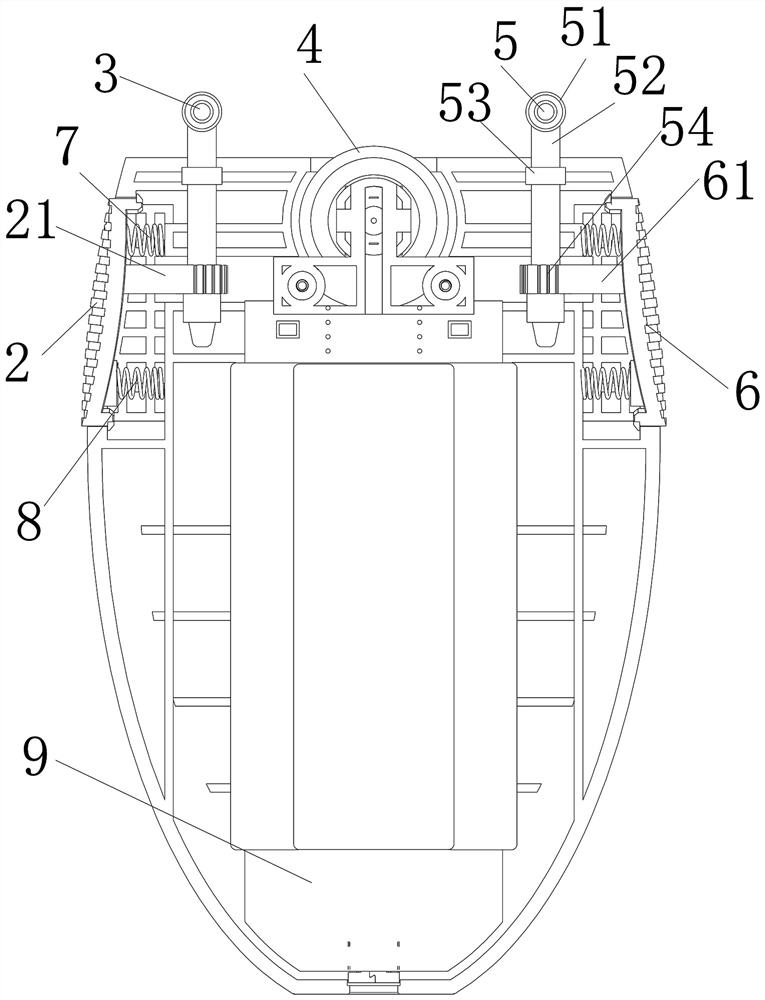
[0077] The structure of the electric curtain control device in the present embodiment is as follows: Figures 1 to 9 As shown, the electric curtain control device is used to cooperate with the internal type track. The curtain control device as a whole includes a housing 1, and the top of the housing 1 is provided with a driving wheel 4, a front driven wheel assembly 3 and a rear driven wheel assembly 5. Most of the driving wheel 4 is located inside the housing, and a small part protrudes from the top of the housing 1, so as to roll and press fit with the lower side of the bottom wall of the inner-shaped track. The front driven wheel assembly 3 and the rear driven wheel assembly The driven wheel 51 on the top of the component 5 protrudes upwards, and is used to extend into the inner cavity of the inner-shaped track, and roll and press fit with the upper side of the bottom wall of the inner-shaped track.

[0078] The structures of the front side driven wheel assembly 3 and the r...

specific Embodiment 2

[0094] It differs from Embodiment 1 mainly in that: in Embodiment 1, both the front transmission mechanism and the rear transmission mechanism are rack and pinion mechanisms. In this embodiment, the front transmission mechanism and the rear transmission mechanism can also be link transmission mechanisms, the link transmission mechanism includes a connecting rod, a transmission disc is arranged on the wheel shaft, one end of the connecting rod is hinged with the transmission disc, and the other end is connected with the assembly The button is hinged. When the button is moved forward and backward, the connecting rod can drive the transmission plate to rotate, and then drive the wheel shaft to rotate back and forth.

[0095] It should be noted that when using the linkage mechanism, attention should be paid to avoid dead point problems, for example: if the rotating shaft reaches the assembly and disassembly position when it is rotated 90° from the working position, the linkage can ...

specific Embodiment 3

[0098] The main difference between it and Embodiment 1 is that in Embodiment 1, the mounting and dismounting buttons on both sides respectively drive the two axles of the driven wheel assembly on both sides to rotate synchronously through different transmission mechanisms. In this embodiment, the axles of the driven wheel assemblies on both sides can be driven by the combined force of the mounting and dismounting buttons on both sides through the synchronous transmission mechanism. The synchronous transmission mechanism here is a rack and pinion transmission mechanism, and the rack and pinion mechanism includes two The two gears on the wheel shaft, the front gear fixedly connected with the front side installation and removal button, the rear side gear fixedly connected with the rear side installation and removal button, the front side gear meshes with the two gears on the two wheel shafts respectively, and the rear side gear is fixedly connected with the rear side installation a...


PUM


Abstract

The invention relates to an electric curtain control device which comprises a shell, a driving wheel, a motor, an electric control assembly, a front side driven wheel assembly and a rear side driven wheel assembly are arranged on the shell, a mounting and dismounting button is arranged on the shell, and the mounting and dismounting button drives wheel shafts of the driven wheel assemblies on the two sides to be switched between a working position and a mounting and dismounting position through a transmission mechanism; a switch button is further installed on the shell and used for being pressed to trigger the electric control assembly, and then the electric control assembly is controlled to supply power to the motor. According to the electric curtain control device provided by the invention, the switch button and the assembly and disassembly button are separately arranged, the switch button is used for controlling on and off, the assembly and disassembly button drives the rotating shaft to rotate through the transmission mechanism so as to realize assembly and disassembly of the electric curtain control device, and the switch button and the assembly and disassembly button are separately arranged and do not interfere with each other; the problems of poor product stability and poor user experience caused by function diversification of control buttons in the prior art can be effectively avoided.

Description

technical field [0001] The invention belongs to the field of curtain opening and closing devices, and in particular relates to an electric curtain control device. Background technique [0002] With the rapid development of communication control technology, smart home system can develop rapidly. In the smart home system, the smart curtain system can realize the automatic control of the curtains, can open and close the curtains according to the time customized by the user, overcome the inconvenience of traditional manual opening and closing of the curtains, and improve the comfort of users using the curtains. [0003] At present, most intelligent curtain systems use electric devices to drag the curtains to realize automatic opening and closing. The structure of the electric device is such as the curtain control device disclosed in the Chinese utility model patent whose authorized announcement number is CN209058744U, which is used to move and be installed on the curtain track ...

Claims


Application Information

Patent Timeline
Patent Type & Authority Applications(China)
IPC IPC(8): A47H5/02A47H15/02
CPCA47H5/02A47H15/02
Inventor 叶龙马涛姜红梅田涵朴郭春林
Owner ULTIMATE IOT (SHANGHAI) TECH LTD
Why Eureka
Try Eureka