
Die for accessory forming machining

A technology of molding processing and mould, which is applied in the field of molds for accessories molding processing, can solve the problems of not easy to transmit noise and aggravate the difficulty of cleaning the staff

Pending Publication Date: 2022-03-04
苏州侑忻精密模具有限公司
View PDF1 Cites 0 Cited by
  • Summary
  • Abstract
  • Description
  • Claims
  • Application Information

AI Technical Summary

Problems solved by technology

[0004] 1. Patent document CN212857394U discloses a stamping mold for auto parts processing, including "die bottom plate, the top surface of the mold bottom plate is fixedly connected with stamping lower die, positioning sleeve and lower sound insulation cover, the stamping lower die and The positioning sleeves are all located inside the lower soundproof cover, and the inner wall of the positioning sleeve is movably connected with a first air extraction plate, and the top surface of the first air extraction plate is fixedly connected with an extrusion tube; through the lower sound insulation cover and the positioning Sleeve, so that when the stamping upper die is pressed down to form the raw material plate on the surface of the stamping lower die, the second air suction plate inside the extruded tube can move inside it, and then the second air suction plate will squeeze the air pressure inside the tube lower, the gas inside the lower sound insulation cover connected with the extraction column can be sucked into the extruded tube, thereby reducing the sound transmission medium in the lower sound insulation cover, making it less likely to conduct noise, and improving the noise reduction effect. It is difficult to clean the surface of the processed mold when some existing molds are used. If the cleaning is not done in time, the raw materials will agglomerate on the mold, which will make it difficult to clean up later, which will aggravate the staff Difficulty in cleaning, with certain limitations in use

Method used


Image

  • Die for accessory forming machining
  • Die for accessory forming machining
  • Die for accessory forming machining

Examples


Embodiment 1

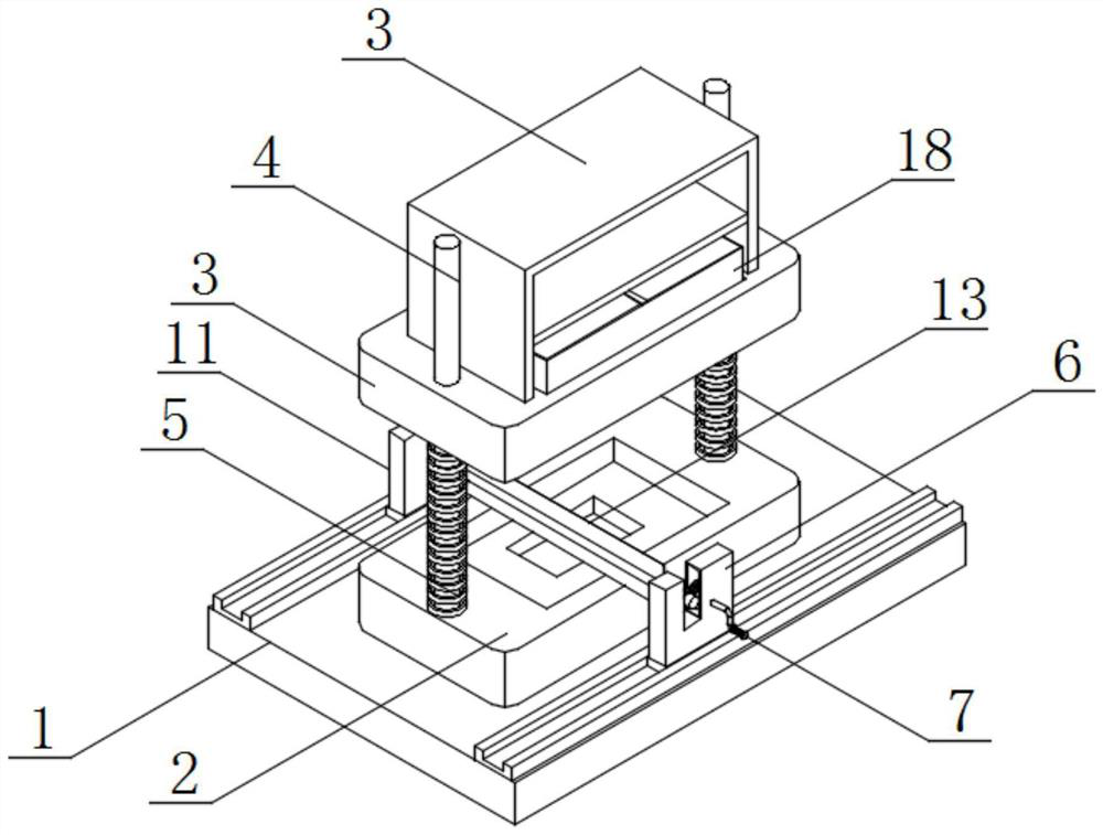
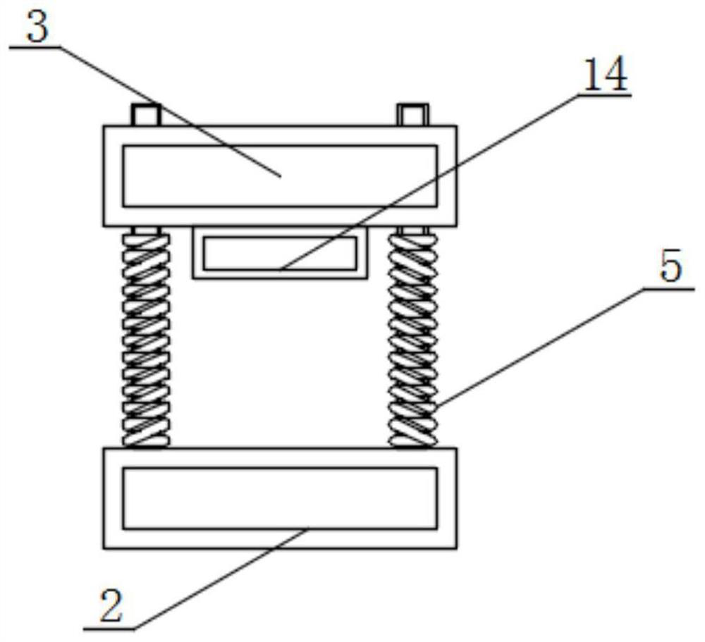
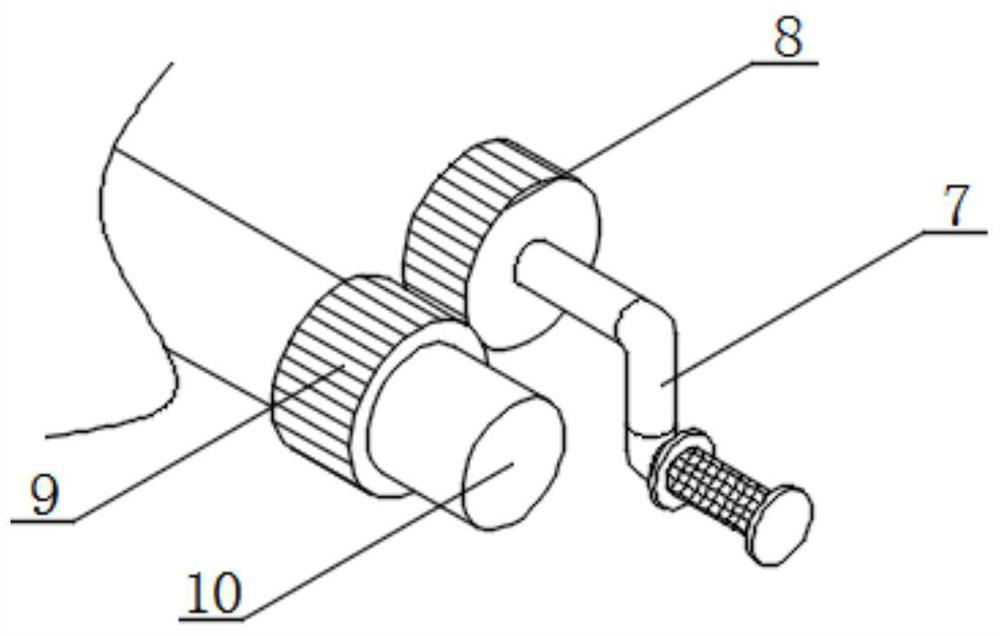
[0027] see figure 1 , figure 2 , image 3 and Figure 5 , an embodiment provided by the present invention, a mold for molding accessories, including a bottom plate 1, a lower mold 2 and an upper mold 3, the top of the bottom plate 1 is provided with a lower mold 2, and both sides of the top of the lower mold 2 are provided with A fixed rod 4, a compression spring 5 runs through the surface of the fixed rod 4, an upper mold 3 is connected to the top of the compression spring 5, a slide rail a is installed on one side of the top of the bottom plate 1, and a slide block a is slidably connected to the inside of the slide rail a, The top of the slider a is provided with a fixed block a6, one side of the fixed block a6 runs through a hand crank 7, the surface of the hand crank 7 runs through a driving gear 8, and the surface of the driving gear 8 is meshed with a driven gear 9. The inside of the gear 9 runs through a rotating rod 10, and the other side of the top of the bottom p...

Embodiment 2

[0031] see figure 1 and Figure 4 , an embodiment provided by the present invention is a mold for accessory molding and processing, a support frame 15 is installed on the top of the upper mold 3, a horizontal plate is installed on the inner side wall of the support frame 15, and a telescopic cylinder 16 is arranged on the top of the horizontal plate. The bottom end of the telescopic cylinder 16 is connected with a pressing plate 17, and the top of the upper mold 3 is provided with an insertion groove, and a cutting frame 18 runs through the inside of the insertion groove;

[0032] The setting of the supporting frame 15, the horizontal plate, the telescopic cylinder 16, the pressing plate 17, the cutting frame 18 and the insertion groove, when the accessories are pressed and formed under the action of the upper mold 3 and the lower mold 2, there will be redundant parts at the corners. The raw material adheres to the edge of the formed product. At this time, the telescopic cyli...


PUM


Abstract

The mold comprises a bottom plate, a lower mold body and an upper mold body, the lower mold body is arranged at the top of a base, fixing rods are arranged on the two sides of the top of the lower mold body, compression springs penetrate through the surfaces of the fixing rods, the upper mold body is connected to the top ends of the compression springs, and a sliding rail a is installed on one side of the top of the bottom plate; a sliding block a is slidably connected into the sliding rail a, a fixing block a is arranged at the top of the sliding block a, a hand crank penetrates through one side of the fixing block a, a driving gear penetrates through the surface of the hand crank, a driven gear is meshed with the surface of the driving gear, and a rotating rod penetrates through the interior of the driven gear. Through the arrangement of the fixing block a, the hand crank, the driving gear, the driven gear, the rotating rod and the scraping plate, residual raw materials on the lower die and the upper die can be scraped, the problem that the subsequent raw materials are hard and formed and are difficult to scrape is avoided, and the fixing rod can play a role in limiting when the upper die and the lower die work.

Description

technical field [0001] The invention relates to the technical field of moulds, in particular to a mold for forming accessories. Background technique [0002] A mold is a tool used to make shaped objects. This tool is composed of various parts. Different molds are composed of different parts. It mainly realizes the processing of the shape of the object through the change of the physical state of the formed material. Some existing molds When processing accessories, there will be redundant scraps at the corners, which will affect the molding effect of the product and have certain limitations in use. [0003] In the prior art, a kind of mold for accessories molding has disadvantages: [0004] 1. Patent document CN212857394U discloses a stamping mold for auto parts processing, including "die bottom plate, the top surface of the mold bottom plate is fixedly connected with stamping lower die, positioning sleeve and lower sound insulation cover, the stamping lower die and The posi...

Claims


Application Information

Patent Timeline
Patent Type & Authority Applications(China)
IPC IPC(8): B21D37/10B21D37/12B08B1/04B21D28/14
CPCB21D37/10B21D37/12B21D28/14B08B1/165B08B1/32
Inventor 姚益伍安东
Owner 苏州侑忻精密模具有限公司
Learn More