Pouring system with slag collecting function and slag collecting method

A pouring system and slag collection technology, which is applied in the direction of manufacturing tools, casting molding equipment, casting molds, etc., can solve problems such as low casting yield, casting structure, performance impact, etc., and achieve the effect of improving product quality

Pending Publication Date: 2022-03-04
山西柴油机工业有限责任公司
View PDF8 Cites 0 Cited by
  • Summary
  • Abstract
  • Description
  • Claims
  • Application Information

AI Technical Summary

Problems solved by technology

[0002] In the production process of aluminum alloy gravity and anti-gravity casting, in order to ensure the quality of the casting and reduce the impurity content in the aluminum liquid, in the gravity casting gating system in the prior art, the method of refining and degassing is usually used to process the aluminum liquid , in order to block the impurities in the molten aluminum, a filter screen is also placed in the gating system, but practice has proved that after the filter screen is placed in the gating system, it is still inevitable that oxidized slag will enter the mold during the pouring process. The slag is usually suspended on the upper surface of the molten metal, and it is easy to enter the mold with the molten metal. The specific reason is that although the molten aluminum enters the runner through the sprue and is filtered through the filter, due to the existence of the drop during the pouring process Oxidized slag will still be generated due to turbulence and turbulent flow, and these oxidized slags will be suspended above the runner, and the floating sand in the gating system will also enter the casting through the inner runner through the inner runner with the flow of aluminum liquid and oxidized slag Cavity, forming slag inclusion defects inside the casting, these defects will have a potential impact on the structure and performance of the casting, and is also the main reason for the low yield of the casting, therefore, it is necessary to improve the existing gating system

Method used


Image

  • Pouring system with slag collecting function and slag collecting method
  • Pouring system with slag collecting function and slag collecting method
  • Pouring system with slag collecting function and slag collecting method

Examples


Embodiment Construction

[0024] It should be noted that, in the case of no conflict, the embodiments of the present invention and the features in the embodiments can be combined with each other.

[0025] In describing the present invention, it should be understood that the terms "center", "longitudinal", "transverse", "upper", "lower", "front", "rear", "left", "right", The orientations or positional relationships indicated by "vertical", "horizontal", "top", "bottom", "inner", "outer", etc. are based on the orientation or positional relationships shown in the drawings, and are only for the convenience of describing the present invention Creation and simplification of description, rather than indicating or implying that the device or element referred to must have a specific orientation, be constructed and operate in a specific orientation, and therefore should not be construed as limiting the invention. In addition, the terms "first", "second", etc. are used for descriptive purposes only, and should no...


PUM


Abstract

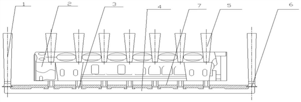
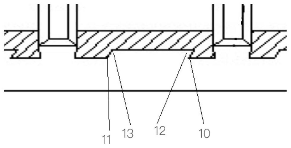
The invention provides a pouring system with a slag collecting function, which comprises a cross gate and a sprue, the upper end of the sprue is used for receiving molten metal of a sprue cup, the lower end of the sprue is communicated with the cross gate, and the middle of the cross gate is communicated with a plurality of ingates; a filter assembly is mounted in the sprue or at the joint of the sprue and the cross gate, and a cover plate core is mounted in the cross gate; the cover plate core is positioned on the upper side of the cross gate, and the lower edge of the cover plate core is lower than the inner gate at the lower end of the ingate; a plurality of slag collecting grooves are formed in the lower surface of the cover plate core; the side wall of the side, close to the inner gate, of each slag collecting groove is of a vertical or inclined blocking structure towards the liquid incoming side, and the side wall of the side, different from the inner gate, of each slag collecting groove is of an inclined guiding structure. According to the casting device, slag inclusion in molten metal is filtered through the filter screen, slag inclusion and floating sand generated in the casting process are filtered again through the slag collecting groove, and therefore the quality of casting products can be effectively improved.

Description

technical field [0001] The invention belongs to the technical field of casting technology, and in particular relates to a pouring system and a slag collecting method with a slag collecting function. Background technique [0002] In the production process of aluminum alloy gravity and anti-gravity casting, in order to ensure the quality of the casting and reduce the impurity content in the aluminum liquid, in the gravity casting gating system in the prior art, the method of refining and degassing is usually used to process the aluminum liquid , in order to block the impurities in the molten aluminum, a filter screen is also placed in the gating system, but practice has proved that after the filter screen is placed in the gating system, it is still inevitable that oxidized slag will enter the mold during the pouring process. The slag is usually suspended on the upper surface of the molten metal, and it is easy to enter the mold with the molten metal. The specific reason is tha...

Claims


Application Information

Patent Timeline
Patent Type & Authority Applications(China)
IPC IPC(8): B22C9/08
CPCB22C9/082B22C9/086
Inventor 王光伟张世武孟祥松刘洪斌王伟张耀
Owner 山西柴油机工业有限责任公司
Why Eureka
Try Eureka