
Vibroflotation construction operator guiding method and system

A technology of operators and working methods, applied in the field of civil engineering, can solve the problems of irregular construction and the ineffective control of the vibro-construction process, and achieve the effect of ensuring integrity and simple operation.

Pending Publication Date: 2022-03-04
成都雅蓝特科技有限公司
View PDF0 Cites 2 Cited by
  • Summary
  • Abstract
  • Description
  • Claims
  • Application Information

AI Technical Summary

Problems solved by technology

The records of the construction process can provide effective technical means for on-site management and supervisors to detect irregular construction in time, so that the overall construction quality is under monitoring. It is used to solve the problem that the existing vibro-construction process cannot be effectively controlled

Method used


Image

  • Vibroflotation construction operator guiding method and system
  • Vibroflotation construction operator guiding method and system
  • Vibroflotation construction operator guiding method and system

Examples


Embodiment 1

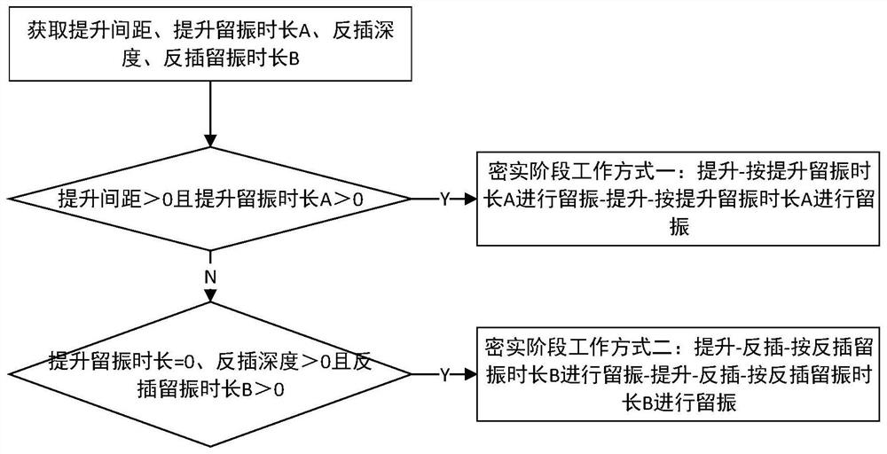
[0074] A vibro-construction operator guidance method specifically includes the following steps:

[0075] S1. Obtain the setting parameters sent by the human-computer interaction interface, the setting parameters include the lifting distance, the lifting vibration duration A, the reverse insertion depth, and the reverse insertion vibration duration B;

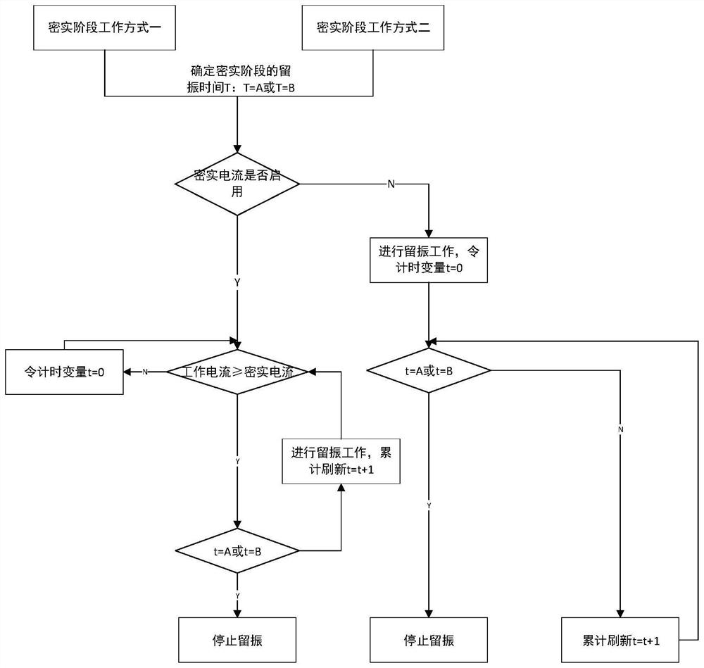
[0076] S2. Judgment is made according to the lifting distance, the lifting vibration duration A, the reverse insertion depth, and the reverse insertion vibration duration B, and different control instructions are issued to make the vibrating device perform vibrating operations in different working modes during the compacting stage. Specifically include the following situations:

[0077] When the lifting distance > 0 and the lifting vibration retention time > 0, the first control instruction is issued to make the vibrator perform vibrating operation in the compacting stage in working mode 1. The working mode 1 is: lifting - accor...

Embodiment 2

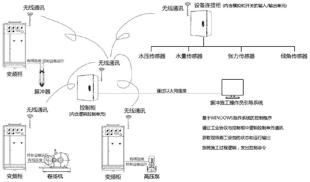
[0111] The purpose of this embodiment is to provide a vibroconstruction operator guidance system, including:

[0112] Acquisition parameter module: used to obtain the setting parameters sent by the human-computer interaction interface, the setting parameters include the lifting distance, the lifting vibration duration A, the reverse insertion depth, and the reverse insertion vibration duration B;

[0113] Determine the working mode module: used to make judgments based on the lifting distance, the lifting vibration duration A, the reverse insertion depth, and the reverse insertion vibration duration B, and issue different control instructions to make the vibro impactor work in different ways during the compaction stage Perform vibrating operations, specifically including the following situations:

[0114] When the lifting distance and the lifting vibration duration > 0, the first control command is issued to make the vibrator perform the vibrating operation in the compacting st...


PUM


Abstract

The invention discloses a vibroflotation construction operator guiding method and system, and the method comprises a human-computer interaction interface, and specifically comprises the steps: S1, obtaining setting parameters sent by the human-computer interaction interface, the setting parameters comprising a lifting distance, a lifting vibration remaining duration A, a reverse insertion depth, and a reverse insertion vibration remaining duration B; and S2, according to the lifting distance, the lifting vibration remaining duration A, the reverse insertion depth and the reverse insertion vibration remaining duration B, judgment is conducted, different control instructions are sent out, and the vibroflot conducts vibroflot operation in different working modes in the compacting stage. Through the human-computer interface, a user can set construction parameters, observe main parameter changes in the construction process and know the construction progress condition. Various working state indicating lamps are further arranged on the interface of the display screen to prompt or give an alarm to the construction state.

Description

technical field [0001] The invention relates to the technical field of civil engineering, in particular to a vibrating construction operator guidance method and system. Background technique [0002] The vibrating gravel pile is a concealed project. In order to effectively fill the punched hole with gravel and other coarse fillers to form the pile body, it must be ensured that the punching depth, vibrating strength, water Parameters such as pressure and vibrating time all meet the design requirements to ensure the construction quality. At present, the control methods for the above-mentioned parameters affecting the quality of gravel piles are as follows: 1. On-site observation and manual control by construction personnel; 2. On-site management or supervisors track the construction process of each pile throughout the process to effectively control the construction quality. Since the construction of vibrating gravel piles is a continuous process, under the condition that the c...

Claims


Application Information

Patent Timeline
Patent Type & Authority Applications(China)
IPC IPC(8): G06Q10/06G06Q10/10G06Q50/02G08B21/24
CPCG06Q10/063114G06Q10/0635G06Q10/103G06Q50/02G08B21/24
Inventor 曹杰舒玉焕伍杉汤雯璐汤勇军汤雯强曹寅亮廖兰
Owner 成都雅蓝特科技有限公司
Learn More