
Switch cabinet capable of being additionally provided with movable bracket

A switch cabinet and mobile technology, applied in the field of switch cabinets, can solve the problems that it is inconvenient for staff to install mobile brackets, switch cabinets are inconvenient to move, inconvenient to install and maintain, etc., so as to facilitate light supplement and improve efficiency , Improve the effect of heat dissipation

Pending Publication Date: 2022-03-04
鼎圣集团电力工程有限公司
View PDF11 Cites 0 Cited by
  • Summary
  • Abstract
  • Description
  • Claims
  • Application Information

AI Technical Summary

Problems solved by technology

[0004] During the use of the existing switchgear, it is inconvenient for the staff to install the mobile bracket, which leads to the inconvenient movement of the switchgear, and in the process of use, it is inconvenient for the staff to install the components inside the switchgear. To solve the problems of installation and maintenance, we propose a switchgear that can be equipped with mobile brackets

Method used


Image

  • Switch cabinet capable of being additionally provided with movable bracket
  • Switch cabinet capable of being additionally provided with movable bracket
  • Switch cabinet capable of being additionally provided with movable bracket

Examples


Embodiment 1

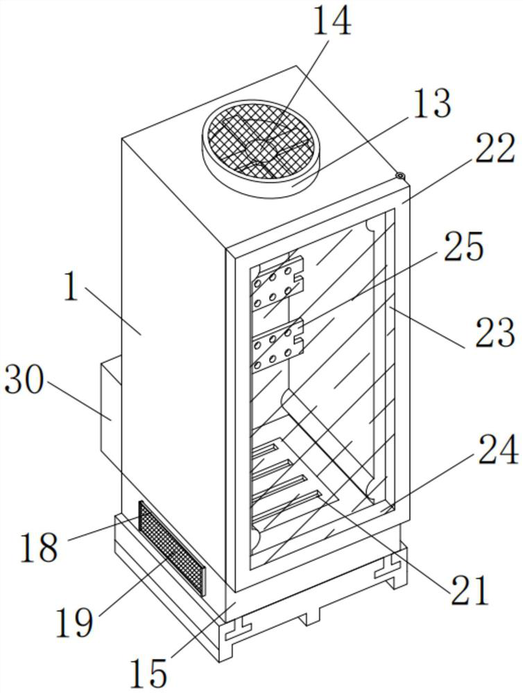
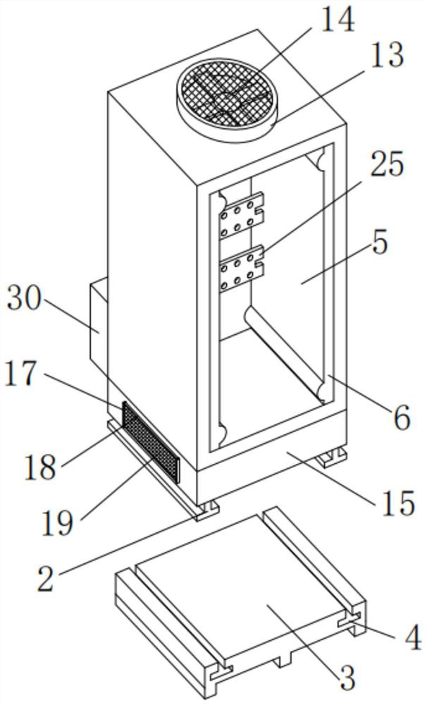
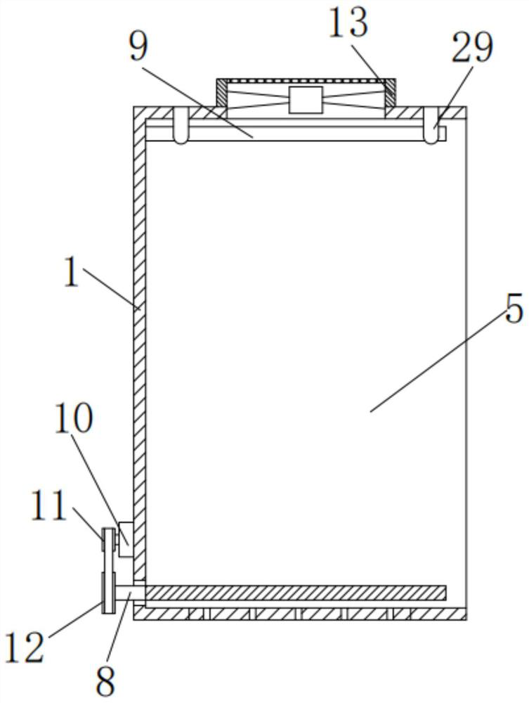
[0031] see Figure 1 to Figure 6 , the present invention provides a technical solution: a switchgear that can be equipped with a movable bracket, including a switchgear body 1, a ventilation box 15 is installed on the bottom outer wall of the switchgear body 1 through bolts, and the ventilation box 15 is used For ventilation during use, two connection blocks 2 are welded on the bottom outer wall of the ventilation box 15, the connection blocks 2 are used to connect with the tray body 3 during use, and the outside of the connection block 2 is slidingly connected with the tray There are two connecting grooves 4 on the top outer wall of the main body 3 and the tray body 3, the connecting grooves 4 are used to connect with the connecting block 2, and the connecting block 2 is slidably connected inside the connecting groove 4, and the inside of the switchgear body 1 is opened. There is a cavity 5, and the inside of the cavity 5 is slidably connected with a mounting frame 6, and the...

Embodiment 2

[0034] see Figure 1 to Figure 6 As shown, on the basis of Embodiment 1, the present invention provides a technical solution for a switchgear that can be equipped with a movable bracket: a fixed ring 13 is welded on the top outer wall of the switchgear body 1, and the inside of the fixed ring 13 passes through The screw is equipped with an exhaust fan 14, and the model of the exhaust fan 14 is preferably BY-B310E-EC-00; both sides of the ventilation box 15 are provided with an air inlet 16, and on the side of the ventilation box 15 The limit bar 17 is installed by screws, the limit bar 17 is located on both sides of the air inlet 16, the top outer wall of the ventilation box 15 has a vent 20, and the bottom inner wall of the switch cabinet body 1 has a vent groove 21, and The ventilation groove 21 communicates with the ventilation port 20 , and the fixing frame 18 is plugged into the inside of the limiting bar 17 , and the inside of the fixing frame 18 is installed with a dust...


PUM


Abstract

The switch cabinet comprises a switch cabinet body, a ventilation box is installed on the outer wall of the bottom of the switch cabinet body through bolts, two connecting blocks are welded to the outer wall of the bottom of the ventilation box, a tray body is slidably connected to the outer portions of the connecting blocks, and two connecting grooves are formed in the outer wall of the top of the tray body; the connecting blocks are slidably connected to the interiors of the connecting grooves, a cavity is formed in the switch cabinet body, and a mounting frame is slidably connected to the interior of the cavity; through arrangement of a connecting block, a connecting groove, a mounting frame and an adjusting screw rod, a worker can conveniently mount and dismount the tray body in the using process through the connecting block and the connecting groove, and then the worker can conveniently load and move the switch cabinet in the using process; and the adjusting screw rod can eject out the mounting rack in the use process, so that a worker can conveniently maintain and mount components in the switch cabinet in the use process.

Description

technical field [0001] The invention belongs to the technical field of switch cabinets, and in particular relates to a switch cabinet which can be equipped with a movable bracket. Background technique [0002] The switch cabinet is a kind of electrical equipment. The outside line of the switch cabinet first enters the main control switch in the cabinet, and then enters the sub-control switch. Each branch is set according to its needs, such as instruments, automatic control, motor magnetic switches, various AC contactors, etc. There is also a high-voltage room and a low-voltage room switch cabinet. [0003] Chinese Patent No. CN201910360935.3 provides a switch cabinet with a movable switch cabinet bracket device, including a bottom plate, four shock absorbing mechanisms are provided at the bottom of the bottom plate, and a moving mechanism is provided at the bottom of the shock absorbing mechanism. A fixing mechanism is provided in the middle of the base plate, a switch cabi...

Claims


Application Information

Patent Timeline
Patent Type & Authority Applications(China)
IPC IPC(8): H02B1/52H02B1/50H02B1/32H02B1/56H02B1/28
CPCH02B1/52H02B1/50H02B1/32H02B1/565H02B1/28
Inventor 张梓康周兴锋
Owner 鼎圣集团电力工程有限公司
Learn More