
A dynamic overheating warning motor

A dynamic, overheating technology, applied in the direction of motors, electric components, electric vehicles, etc., can solve the problems of poor motor stability, heat dissipation, life impact, etc., and achieve the effect of reducing the life of the motor and the impact of operation stability

Active Publication Date: 2022-04-12
睢宁核源风力发电有限公司
View PDF4 Cites 0 Cited by
  • Summary
  • Abstract
  • Description
  • Claims
  • Application Information

AI Technical Summary

Problems solved by technology

[0003] When the motor is working, the rotor rotates at high speed, which will cause the motor to generate a lot of heat. In the prior art, heat dissipation scales are usually arranged on the surface of the motor to increase the heat dissipation area and achieve the effect of heat dissipation. However, when the motor is continuously working, it will generate a lot of heat. , especially for large motors, it is difficult to dissipate the heat in time only through the heat dissipation scales, and in the existing technology, it is difficult for the staff to perform manual intervention in time when the temperature is close to or higher than the stable operating temperature, and it is difficult to alleviate the abnormal rise in time temperature, resulting in poor stability of the motor during operation, and working under abnormal temperature for a long time will also have a certain impact on its life

Method used

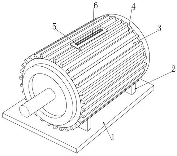
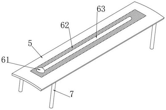
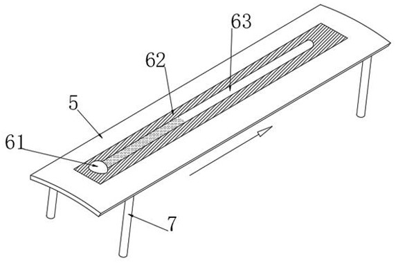

Image

  • A dynamic overheating warning motor
  • A dynamic overheating warning motor
  • A dynamic overheating warning motor

Examples


Embodiment Construction

[0032] The technical solutions in the embodiments of the present invention will be described clearly and completely in conjunction with the accompanying drawings in the embodiments of the present invention below; obviously; the described embodiments are only some embodiments of the present invention; rather than all embodiments, based on The embodiments in the present invention; all other embodiments obtained by those skilled in the art without creative efforts; all belong to the protection scope of the present invention.

[0033] In the description of the present invention, it should be noted that the orientations or positional relationships indicated by the terms "upper", "lower", "inner", "outer", "top / bottom" etc. are based on the orientations shown in the drawings Or positional relationship is only for the convenience of describing the present invention and simplifying the description, but does not indicate or imply that the device or element referred to must have a specif...


PUM


Abstract

The invention discloses a dynamic overheating early warning motor, which belongs to the field of electric motors. Through the setting of the color delay warning bar, when the temperature is close to the stable operating temperature, the color delay layer gradually heats up and presents a flow state, thereby extending along the color delay warning bar. At the same time, the bamboo-shaped stacked tube is extended and the pneumatic ball is pushed to accelerate the flow of the color extension layer, so that the color change can be quickly presented visually, and the staff can be visually reminded that there may be a risk of abnormal temperature rise in the motor, which is convenient for them to carry out manual work in time. Intervention to reduce the impact of abnormal high temperature on motor life and operation stability. At the same time, when the colored magnetic powder on the pneumatic ball is exposed and gradually adsorbed on the inner wall of the color delay warning strip, it means that the surface temperature of the motor is higher than the safe operating temperature, which is convenient for the staff. The temperature of the motor is judged at this time, so that manual intervention can be carried out in time.

Description

technical field [0001] The invention relates to the field of motors, more specifically, to a dynamic overheating warning motor. Background technique [0002] Motor (commonly known as "motor") refers to an electromagnetic device that realizes the conversion or transmission of electric energy according to the law of electromagnetic induction. [0003] When the motor is working, the rotor rotates at high speed, which will cause the motor to generate a lot of heat. In the prior art, heat dissipation scales are usually arranged on the surface of the motor to increase the heat dissipation area and achieve the effect of heat dissipation. However, when the motor is continuously working, it will generate a lot of heat. , especially for large motors, it is difficult to dissipate the heat in time only through the heat dissipation scales, and in the existing technology, it is difficult for the staff to perform manual intervention in time when the temperature is close to or higher than t...

Claims


Application Information

Patent Timeline
Patent Type & Authority Patents(China)
IPC IPC(8): H02K11/25G08B5/18H02K5/18
CPCH02K11/25G08B5/18H02K5/18H02K2213/03H02K2213/09Y02T10/64
Inventor 史瑞台运河
Owner 睢宁核源风力发电有限公司
Learn More