Check patentability & draft patents in minutes with Patsnap Eureka AI!

Ultrasonic Lamb wave logging well wall acoustic interface reverse time migration imaging method

A reverse time migration imaging and ultrasonic technology, which is used in earth-moving drilling, construction, etc., can solve the problems such as the inability to obtain the accurate position of the acoustic interface of the borehole wall, the failure of the A0 reflected wave to converge, and the influence of the amplitude of the A0 reflected wave.

Active Publication Date: 2022-03-08
UNIV OF ELECTRONICS SCI & TECH OF CHINA
View PDF10 Cites 0 Cited by
  • Summary
  • Abstract
  • Description
  • Claims
  • Application Information

AI Technical Summary

Problems solved by technology

[0004] However, in practical applications, the conventional ultrasonic Lamb data processing method is difficult to provide complete information on the second and third acoustic interfaces of the borehole wall, and can only qualitatively judge the attenuation information of the casing medium, which mainly has the following two problems:
[0005] 1) The eccentricity of the casing or the instrument will affect the amplitude of the leaked A0 reflection wave at the cement-formation interface, and the cement-formation interface cannot be directly observed from the waveform data;
[0006] 2) The complex downhole environment makes it impossible for us to perform time-position conversion through obliquely incident ultrasonic Lamb wave data, and it is difficult to convert the leaked A0 reflected wave signal in the time domain to its distance from the well axis. The A0 reflected wave cannot converge, and the well Accurate location of wall-acoustic interface (borehole wall and cement, cement and formation)
[0008] However, the leaked A0 mode waves produced by the oblique incidence of ultrasonic Lamb waves have a certain dispersion. Directly using conventional reverse time migration and imaging conditions will produce interface imaging artifacts at multiple positions, and the reflected waves and diffracted waves cannot be shifted and homing.
In addition, the current ultrasonic Lamb wave logging adopts oblique incidence single-shot-double-receive technology, and each depth point only contains the measurement waveform results of the far and near two geophones, and the reverse time migration algorithm cannot be used

Method used


Image

  • Ultrasonic Lamb wave logging well wall acoustic interface reverse time migration imaging method
  • Ultrasonic Lamb wave logging well wall acoustic interface reverse time migration imaging method
  • Ultrasonic Lamb wave logging well wall acoustic interface reverse time migration imaging method

Examples


Embodiment 1

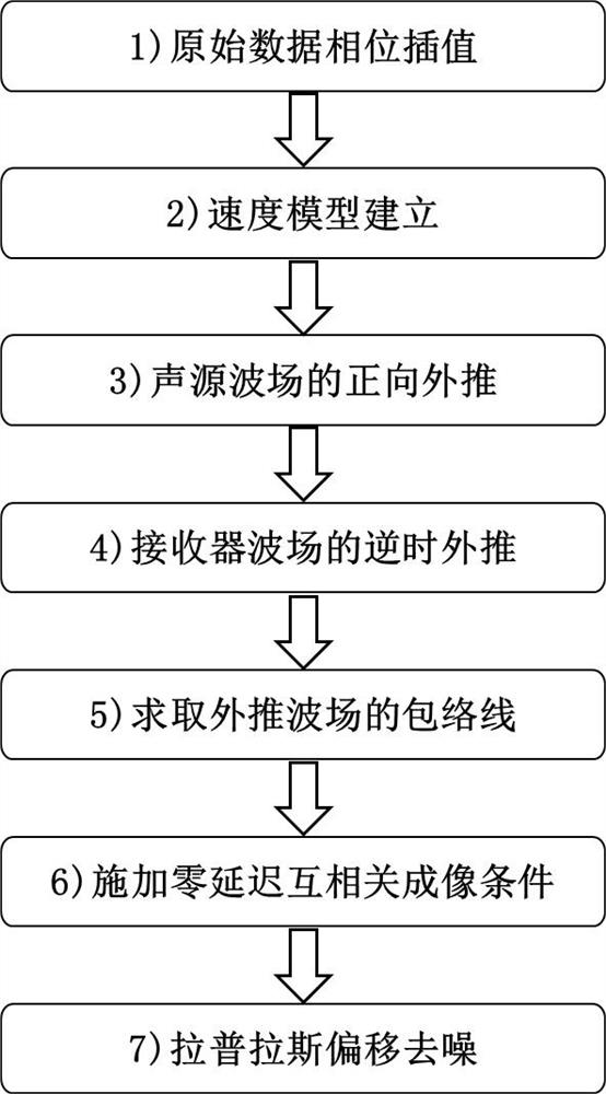
[0061] In this example, if figure 1 As shown, a reverse time migration imaging method of acoustic interface of ultrasonic Lamb wave logging borehole wall includes the following steps:

[0062] Step1: Raw data input and A0 mode wave phase interpolation:

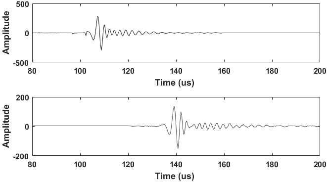
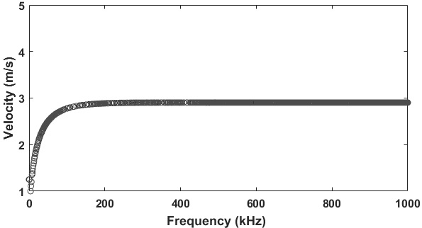
[0063] Input the raw data of ultrasonic Lamb wave logging and the velocity of fluid in the well, casing thickness, casing longitudinal wave and shear wave velocity and center frequency parameters, and calculate the theoretical dispersion curve of A0 mode wave. Based on the phase velocity of A0 mode wave, the phase shift is adopted method to obtain the waveform of a certain receiver's waveform traveling forward or backward for a certain distance:

[0064] g(t)=∫F(w)H(w)e -jwt dw

[0065]

[0066] Among them, g(t) is the propagation distance x 0 After the waveform, F(w) is the spectrum of the original A0 mode wave signal, w is the angular frequency, e is the natural logarithm, H(w) is the propagation matrix, and k is the ...

Embodiment 2

[0093] This embodiment is an implementation case of simulating ultrasonic Lamb wave logging data, and the specific trial calculation process is as follows:

[0094] (1) Read in the ultrasonic Lamb wave logging simulated wave field record (SimulatedLamb.dat), and input the fluid velocity and density in the well, casing density, casing P-wave velocity, casing S-wave velocity, cement density, cement P-wave velocity, and cement S-wave Velocity, formation density, formation compressional wave velocity, formation shear wave velocity.

[0095] (2) Calculate the theoretical dispersion curve of the A0 mode wave, perform phase interpolation on the original ultrasonic Lamb wave data, and expand the original two detector data into array waveform data.

[0096] (3) Set the grid size and model size, and establish the initial velocity model of the target area.

[0097] (4) Based on the two-dimensional high-order staggered grid finite difference and non-split perfect matching layer, the ultr...

Embodiment 3

[0102] This embodiment is an implementation case of the actual measurement of ultrasonic Lamb wave calibration well data, and the specific trial calculation process is as follows:

[0103](1) Read in the simulated wave field records of ultrasonic Lamb wave logging, and input the fluid velocity and density in the well, casing density, casing P-wave velocity, casing S-wave velocity, cement density, cement P-wave velocity, cement S-wave velocity, formation density, Formation compressional wave velocity, formation shear wave velocity.

[0104] (2) Calculate the theoretical dispersion curve of the A0 mode wave, perform phase interpolation on the original ultrasonic Lamb wave data, and expand the original two detector data into array waveform data.

[0105] (3) Set the grid size and model size, and establish the initial velocity model of the target area.

[0106] (4) Based on the two-dimensional high-order staggered grid finite difference and non-split perfect matching layer, the u...


PUM


Abstract

The invention discloses an ultrasonic Lamb wave well wall acoustic interface reverse time migration imaging method comprising the following steps: calculating a theoretical frequency dispersion curve, carrying out phase interpolation on original data, and expanding original detector data into array waveform data; establishing an initial density, longitudinal wave and transverse wave velocity model of the target area; forward extrapolation is carried out on the sound source wave field, and a forward extrapolation wave field is stored; inverting the time axis, performing reverse time extrapolation on the receiver wave field, and storing a reverse time extrapolation wave field; solving an envelope line of a forward extrapolation wave field and an extrapolation wave field; applying a zero-delay cross-correlation time consistency imaging condition to obtain a reverse time migration imaging result; and performing imaging denoising on the result, and enhancing the imaging result of the high-frequency acoustic interface. According to the method, the ultrasonic Lamb oblique incidence waveform offset can be classified to the real position, the imaging illusion caused by Lamb wave frequency dispersion is suppressed, the acoustic interface imaging results between the casing and the cement and between the cement and the stratum are obtained, and a powerful guarantee is provided for evaluating the well cementation quality.

Description

technical field [0001] The invention relates to the technical field of cementing quality evaluation, in particular to a reverse-time migration imaging method of an ultrasonic Lamb wave logging borehole wall acoustic interface. Background technique [0002] The exploitation of oil and gas, geothermal and groundwater, the construction of gas storage, and the storage of carbon dioxide all require casings to be placed in the wellbore, and cement is injected between the casing and the well wall to ensure the integrity of the wellbore and realize interlayer and Hydraulic isolation. The annular space between the rock wall of an oil and gas well and the steel casing in the well is usually filled with different types of cement for well wall protection and isolation between rock layers at different depths. In this structure, damages such as casing corrosion and quality problems of cement bonding outside the pipe will have a significant impact on the production of oil and gas wells. ...

Claims


Application Information

Patent Timeline
Patent Type & Authority Applications(China)
IPC IPC(8): E21B47/005
CPCE21B47/005E21B2200/20G01V1/28G01V2210/51Y02A90/30E21B47/14G01V1/50G01V2210/6242
Inventor 王华李萌
Owner UNIV OF ELECTRONICS SCI & TECH OF CHINA
Features
  • R&D
  • Intellectual Property
  • Life Sciences
  • Materials
  • Tech Scout
  • Unparalleled Data Quality
  • Higher Quality Content
  • 60% Fewer Hallucinations
Learn More