Supercharge Your Innovation With Domain-Expert AI Agents!

FinFET device and forming method of gate structure thereof

A gate structure and device technology, applied in semiconductor devices, semiconductor/solid-state device manufacturing, electrical components, etc., can solve problems such as dummy gates are easy to remain and affect product yield, so as to prevent excessive offset and improve yield Effect

Pending Publication Date: 2022-03-08
SHANGHAI INTEGRATED CIRCUIT EQUIP & MATERIALS IND INNOVATION CENT CO +1
View PDF0 Cites 0 Cited by
  • Summary
  • Abstract
  • Description
  • Claims
  • Application Information

AI Technical Summary

Problems solved by technology

It should be noted that the above-mentioned reduced window 240' will have adverse effects in many subsequent processes. For example, when the dummy gate is removed, the dummy gate is very likely to remain in the window 240', thereby affecting the product yield.

Method used


Image

  • FinFET device and forming method of gate structure thereof
  • FinFET device and forming method of gate structure thereof
  • FinFET device and forming method of gate structure thereof

Examples


Embodiment Construction

[0032] In order to make the purpose, advantages and features of the present invention clearer, the present invention will be further described in detail below in conjunction with the accompanying drawings and specific embodiments. It should be noted that the drawings are all in very simplified form and not drawn to scale, and are only used to facilitate and clearly assist the purpose of illustrating the embodiments of the present invention. In addition, the structures shown in the drawings are often a part of the actual structures. In particular, each drawing needs to display different emphases, and sometimes uses different scales.

[0033] As used in the present invention, the singular forms "a", "an" and "the" include plural objects, the term "or" is usually used in the sense of including "and / or", and the term "several" Usually, the term "at least one" is used in the meaning of "at least one", and the term "at least two" is usually used in the meaning of "two or more". In ...


PUM

PropertyMeasurementUnit
thicknessaaaaaaaaaa
thicknessaaaaaaaaaa

Abstract

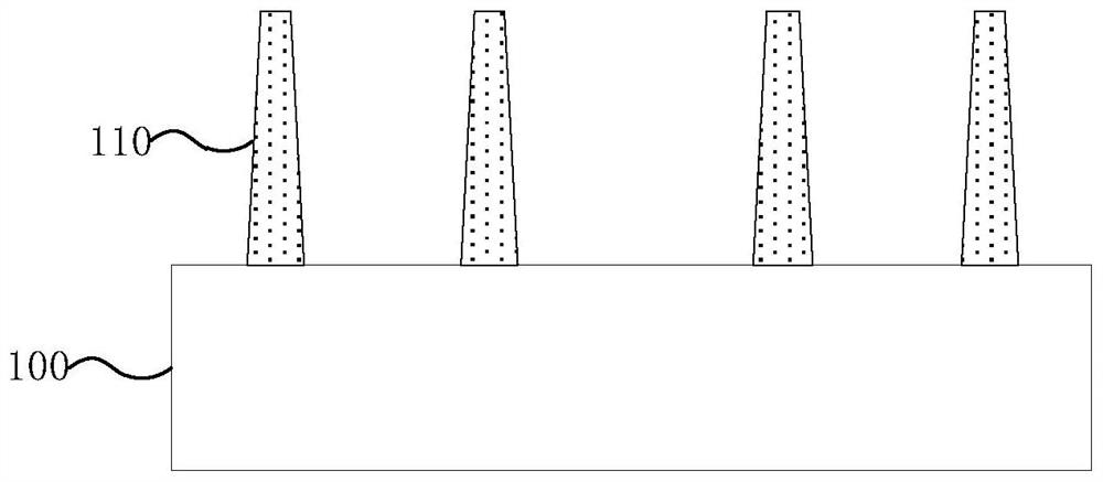
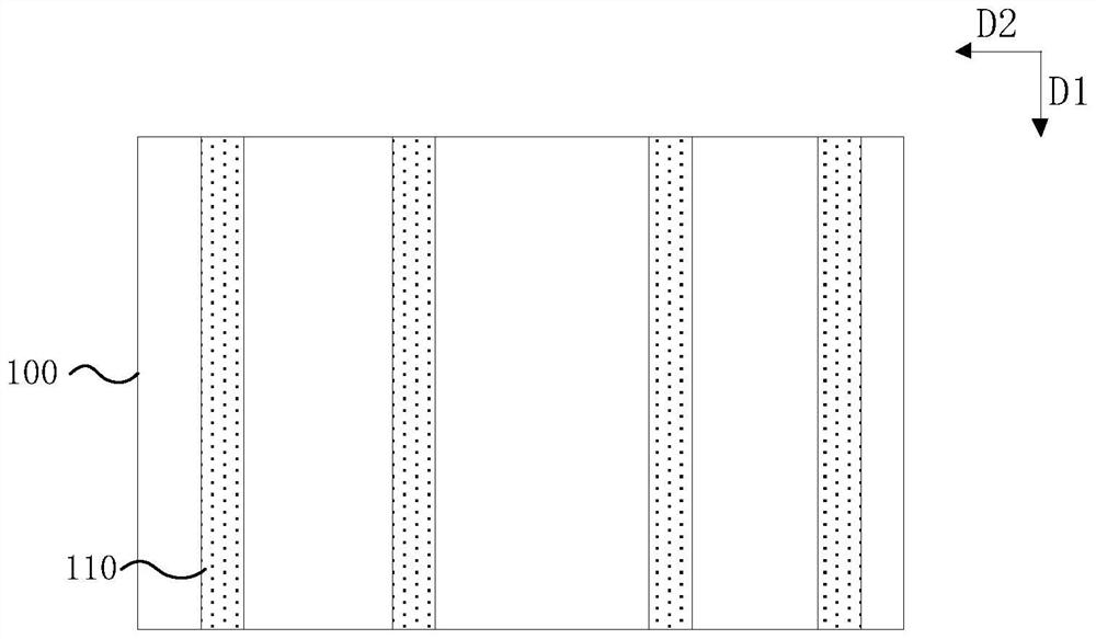
The invention provides a method for forming a gate structure of a FinFET device, and the method comprises the steps: providing a substrate, and forming fins on the substrate; a sacrificial layer and a stop layer are sequentially formed, the sacrificial layer covers the outer walls of the fins and the surface of the substrate, and the stop layer covers the sacrificial layer; forming a virtual grid electrode, wherein the virtual grid electrode partially covers the isolation layer and the substrate; etching a part of the virtual gate to form a deep groove exposing the substrate, forming an isolation wall in the deep groove, and cutting off the virtual gate by the isolation wall; and removing the virtual gate, the stop layer and the sacrificial layer to form a gate structure. By using the sacrificial layer and the stop layer covering the fin, the distance between the deep groove and the fin can be ensured by using the stop layer when the virtual gate is etched to form the deep groove, so that the isolation wall formed in the deep groove keeps a proper distance from the fin to have an effect similar to self-alignment, the isolation wall is prevented from excessively shifting, and the reliability of the device is improved. And the yield of the subsequent process can be improved.

Description

technical field [0001] The invention relates to the technical field of integrated circuit manufacturing, in particular to a method for forming a FinFET device and a gate structure thereof. Background technique [0002] With the continuous development of semiconductor technology, traditional planar devices have been difficult to meet people's demand for high-performance devices. Fin Field Effect Transistor (Fin-Field-Effect-Transistor, FinFET) is a three-dimensional device, including fins formed vertically on the substrate and a high dielectric constant metal gate (HKMG) intersecting the fins. The design can greatly improve circuit control and reduce leakage current, and can also greatly shorten the gate length of transistors. [0003] Currently, a replacement metal gate (RMG) process is usually used to form the gate structure, for example, a dummy gate (also called a dummy gate) is formed first, and then the dummy gate is removed to form the gate structure. Please refer to...

Claims


Application Information

Patent Timeline
Patent Type & Authority Applications(China)
IPC IPC(8): H01L21/28H01L21/336
CPCH01L29/66795H01L29/401
Inventor 刘洋
Owner SHANGHAI INTEGRATED CIRCUIT EQUIP & MATERIALS IND INNOVATION CENT CO
Features
  • R&D
  • Intellectual Property
  • Life Sciences
  • Materials
  • Tech Scout
  • Unparalleled Data Quality
  • Higher Quality Content
  • 60% Fewer Hallucinations
Learn More