Supercharge Your Innovation With Domain-Expert AI Agents!

a ball valve

A technology for ball valves and valve stems, which is applied in the direction of valve devices, cocks including cut-off devices, mechanical equipment, etc., which can solve the problem of poor sealing performance and easy movement of the valve core (the valve stem and other structures will also move together, reducing the life of the sealing structure. and other problems, to achieve reasonable structure, guarantee the sealing effect and service life, and alleviate the effect of incorrect air pressure

Active Publication Date: 2019-10-25
HANGZHOU JINSHAN INSTR VALVE IND
View PDF5 Cites 0 Cited by
  • Summary
  • Abstract
  • Description
  • Claims
  • Application Information

AI Technical Summary

Problems solved by technology

However, we know that when the ball valve is closed, the air pressure on both sides of the valve core is not equal (one side is obviously higher than the other side, which is caused by the presence of air pressure), which causes the valve core to move easily ( The structure such as the valve stem will also move together), which will easily lead to poor sealing performance and seriously reduce the life of the sealing structure

Method used


Image

  • a ball valve
  • a ball valve
  • a ball valve

Examples


Embodiment 1

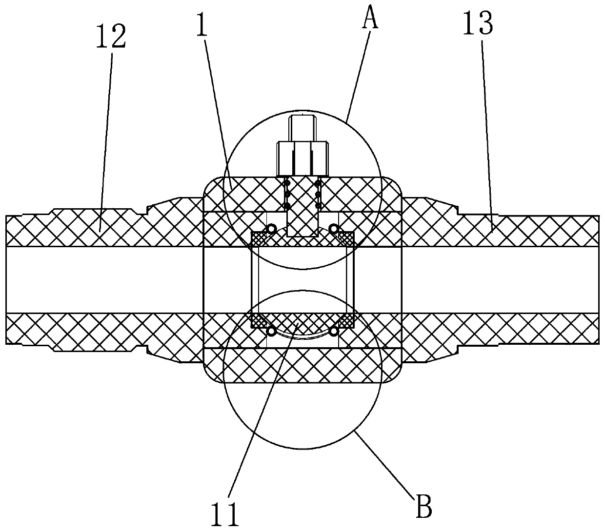
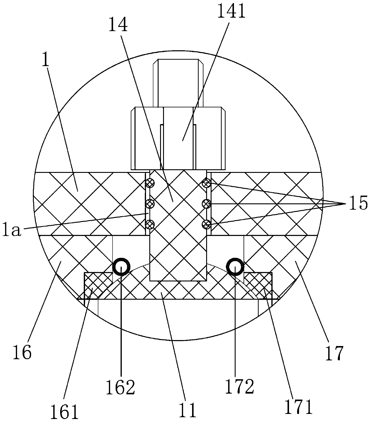
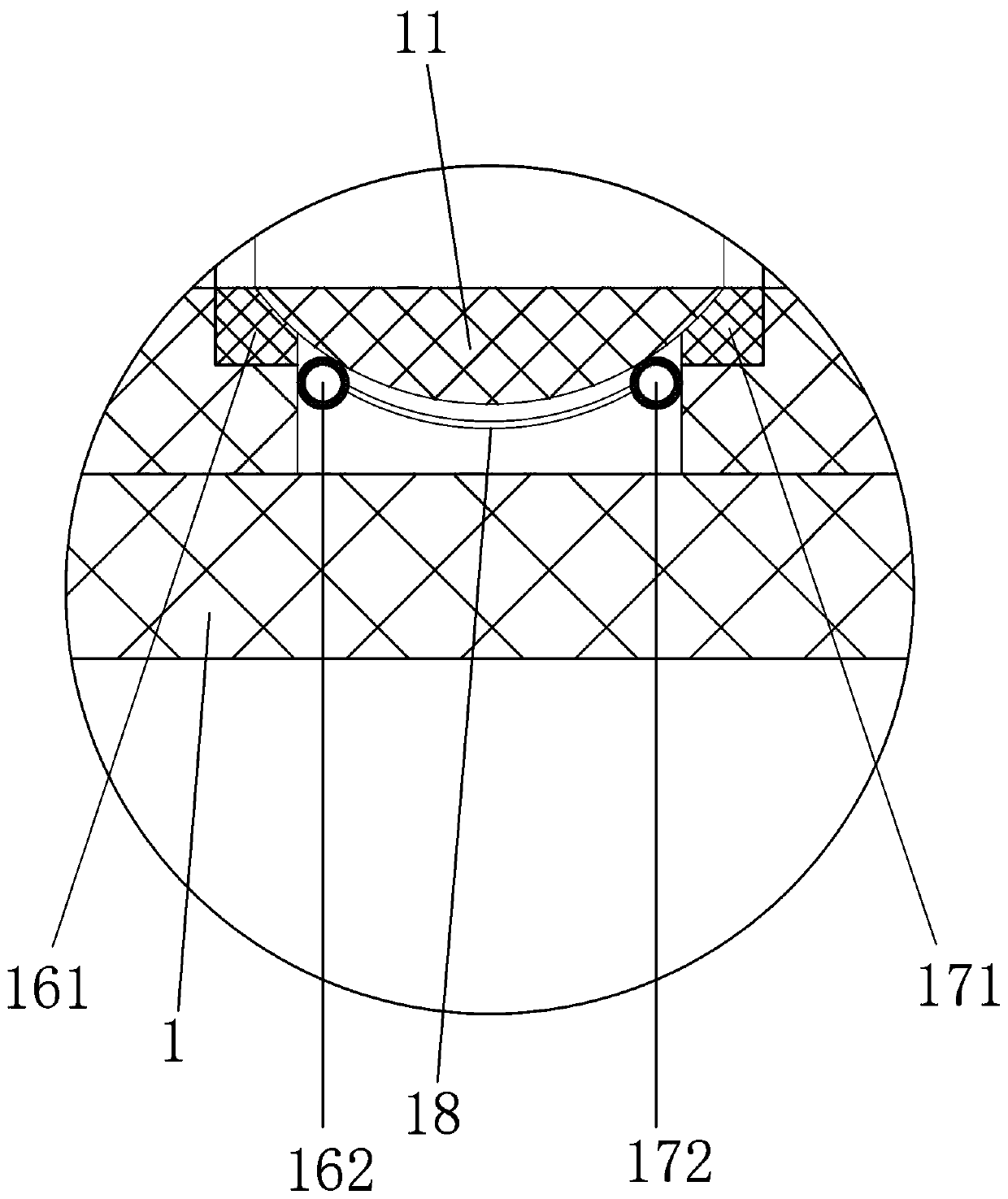
[0027] Embodiment 1: as Figure 1 to Figure 3 as shown,

[0028] Embodiment 1: a kind of ball valve, comprises

[0029] Valve seat 1, valve core 11, left connecting pipe 12, right connecting pipe 13 and valve stem 14 for driving the valve core, the valve seat is provided with a rod hole 1a, the valve stem passes through the rod hole, and the diameter of the rod hole is larger than that of the valve stem Diameter, the valve seat is provided with a channel in the valve, one end of the channel in the valve is connected to the left port, the other end of the channel in the valve is connected to the right port, the seat is provided with a left sealing seat 16 and a right sealing seat 17, and the left sealing seat is provided with There is a valve left sealing ring 161 that is tightly matched with the valve core, and a valve right sealing ring 171 that is tightly matched with the valve core is arranged on the right sealing seat. Between the right connecting pipe and the spool;

...

Embodiment 2

[0038] Embodiment 2: based on embodiment 1, such as Figure 4 to Figure 9 as shown,

[0039] The left connecting pipe is provided with a release structure, and the release structure includes a vertically arranged first release pipe 21, a horizontally arranged release second pipe 22, a vertically arranged release third pipe 23, and a set on the release third pipe. Diffuse valve 231, the bottom of the left connecting pipe is provided with a bottom release hole, the top of the second release pipe is provided with a top release hole 22a, the upper end of the first release pipe is connected to the bottom release hole, the lower end of the first release pipe is connected to the top release hole, and the second release pipe is connected to the top release hole. One end of the tube communicates with the lower end of the third diffuser tube;

[0040]The other end of the second pipe for dispersing is provided with a drawer 3, one end of the drawer is a closed end outside the second pip...


PUM


Abstract

The invention discloses a ball valve. The ball valve comprises a valve seat, a valve core, a left connection pipe, a right connection pipe and a valve rod, wherein the valve seat is internally provided with a left seal seat and a right seal seat, the left seal seat is provided with a left seal ring, the right seal seat is provided with a right seal ring, an inner partition cavity is internally provided with a left pressure regulating seal ring and a right pressure regulating seal ring, the left pressure regulating seal ring is internally provided with a left air inflation cavity, the right pressure regulating seal ring is internally provided with a right air inflation cavity, the left air inflation cavity communicates with the right air inflation cavity through an inner air pipe, the innerair pipe is located inside the inner partition cavity, the left pressure regulating seal ring is fixed with the left seal seat, the valve core holds the left pressure regulating seal ring and the right pressure regulating seal ring down, and in the valve inner passage axial direction, the left seal seat, the left pressure regulating seal ring, the valve rod, the right pressure regulating seal ring and the right seal seat are arranged in sequence. The ball valve has the beneficial effects that the structure is reasonable, opening and closing are performed conveniently and fast, negative influence caused by incoordinate air pressure on two sides of the valve core can be effectively alleviated, and the seal effect and the service life can be effectively guaranteed.

Description

technical field [0001] The invention belongs to the technical field of valves, in particular to a ball valve. Background technique [0002] Ball valve (ball valve), the opening and closing part (ball / spool) is driven by the valve stem and rotates around the axis of the valve core, which can be used for fluid regulation and control. This type of valve should generally be installed horizontally in the pipeline. At present, in the field of gas transportation (such as natural gas pipeline system), ball valves are widely used. However, we know that when the ball valve is closed, the air pressure on both sides of the valve core is not equal (one side is obviously higher than the other side, which is caused by the presence of air pressure), which causes the valve core to move easily ( Structures such as the valve stem will also move together), which will easily lead to poor sealing performance and seriously reduce the life of the sealing structure. Contents of the invention ...

Claims


Application Information

Patent Timeline
Patent Type & Authority Patents(China)
IPC IPC(8): F16K5/06F16K5/08
CPCF16K5/0689F16K5/08
Inventor 陈永杰
Owner HANGZHOU JINSHAN INSTR VALVE IND
Features
  • R&D
  • Intellectual Property
  • Life Sciences
  • Materials
  • Tech Scout
  • Unparalleled Data Quality
  • Higher Quality Content
  • 60% Fewer Hallucinations
Learn More