Special riveting point device for fork pocket joint

A technology of riveting points and fork grooves, which is applied in the field of special riveting point devices for fork groove joints, which can solve the problems of increased manufacturing costs, press-fitting adapter covers that cannot meet the needs of the market, and large grease consumption.

Pending Publication Date: 2022-03-11
耐世特凌云驱动系统(涿州)有限公司
View PDF0 Cites 0 Cited by
  • Summary
  • Abstract
  • Description
  • Claims
  • Application Information

AI Technical Summary

Problems solved by technology

At present, the fork groove section uses a press-fit adapter cover to prevent the steel ball from falling off. This design results in a significant increase in the weight of the half shaft, high grease consumption, and in

Method used


Image

  • Special riveting point device for fork pocket joint
  • Special riveting point device for fork pocket joint
  • Special riveting point device for fork pocket joint

Examples


Embodiment Construction

[0013] The present invention will be further described below in conjunction with specific embodiments.

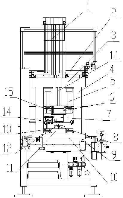
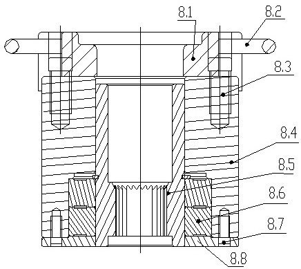
[0014] Such as Figure 1 to 4 As shown, the present embodiment includes bed 2, a table 10, a base 11, a rivet-pressed plate device 7, a lower positioning device 8, and a ball positioning device 14. The lower positioning device 8 is fixed to the base 11, and its inner cavity is a fork tank mounting hole, and the fork tank is rotatable. The bulb positioning device 14 includes a positioning bracket 13, a slide rail 14.1, a reset spring (not shown in the figure), the connecting plate 14.2, the proximity switch 16, the transition plate 14.6, the mounting plate 14.7, the positioning head 14.8 and the handle 14.9. The positioning bracket 13 is fixed to the table 10 by the screw, and the upper end is fixed to the slide guide rail 14.1. The connecting plate 14.2 can be slidably coupled to the slider guide rail 14.1, and is fixed to the bed sidewall by the reset spring, and there is a pro...


PUM


Abstract

A lower positioning device is fixed on a base, an inner cavity of the lower positioning device is a fork pocket section mounting hole, and the fork pocket section can rotate after being mounted; sliding seat guide rails are fixed at the upper ends of the positioning brackets; the connecting plate is connected to the sliding seat guide rail in a horizontal sliding manner, a proximity switch is fixed on the connecting plate, a transition plate is fixed on the connecting plate in an up-down moving manner, and three or six positioning ball heads are uniformly fixed on the lower end surface of a mounting plate fixed on the transition plate; four stand columns of the riveting point pressing disc device are fixed to the workbench, a supporting plate is fixed to the upper ends of the four stand columns, a TOX gas-liquid boosting cylinder is fixed to the supporting plate, and four guide rods are fixed to the lower end of the supporting plate. The sliding plate slides along the guide rod, and the upper end of the sliding plate is fixed on a lever of the TOX gas-liquid boosting cylinder; the riveting point pressure plate is fixed at the lower end of the sliding plate, and six riveting point punches are arranged on the lower end face. Under the condition that any weight is not increased, the steel ball can be reliably prevented from falling off, the requirement for light weight of the half shaft is met, and the manufacturing cost is reduced.

Description

Technical field [0001] The present invention belongs to the processing and manufacturing of the fork tank, which relates to a special rivet device for a fork tank. Background technique [0002] In particular in the high-end sedan, the vehicle is used to deliver power and torque, which is a critical portion of the high-speed rotating drive shaft part. In order to improve the half-axis durability and reduce NVH, most of the high-grade car drive shaft is designed. At present, the fork tank is used to prevent steel balls from falling off, which results in a significant increase in semi-axis weight, and increased oil consumption and increased manufacturing cost. As people's demand for vehicles, and the gradual increase in the half-axis production, the design of the press-fitting cover is far from meeting the needs of the market. Inventive content [0003] It is an object of the present invention to solve the above problems present in the prior art, providing a fork-groove section spe...

Claims


Application Information

Patent Timeline
IPC IPC(8): B23P19/027
CPCB23P19/027
Inventor 谭亚刘念李润泽李旭田句任鹤崔春来
Owner 耐世特凌云驱动系统(涿州)有限公司
Why Eureka
Try Eureka