
Aluminum alloy profile machining tool and clamping mechanism thereof

A clamping mechanism and profile technology, applied in metal processing machinery parts, metal processing equipment, clamping and other directions, can solve the problems of reducing the safety performance of equipment, the danger of manual cleaning, the separation of aluminum alloy profiles from the clamping mechanism, etc. Practicality, increased fixation, increased safety effects

Pending Publication Date: 2022-03-11
李文红
View PDF0 Cites 0 Cited by
  • Summary
  • Abstract
  • Description
  • Claims
  • Application Information

AI Technical Summary

Problems solved by technology

[0006] The invention provides a tooling for processing aluminum alloy profiles and its clamping mechanism. One of the purposes is to have the function of automatically cleaning debris, so as to solve the problem that debris is easy to remain and fall off when the processing device cuts aluminum alloy profiles. Falling on the processing table, manual cleaning is more dangerous, thereby reducing the safety performance of the equipment; another purpose is to solve the problem that the clamping mechanism of the processing device has low fixing performance, which may easily cause the aluminum alloy profile to break away from the clamping mechanism during cutting , thereby reducing the cutting efficiency of the device and affecting the practicability of the device, so as to achieve the effect of increasing the fixation of the clamping mechanism

Method used


Image

  • Aluminum alloy profile machining tool and clamping mechanism thereof
  • Aluminum alloy profile machining tool and clamping mechanism thereof
  • Aluminum alloy profile machining tool and clamping mechanism thereof

Examples


Embodiment 1

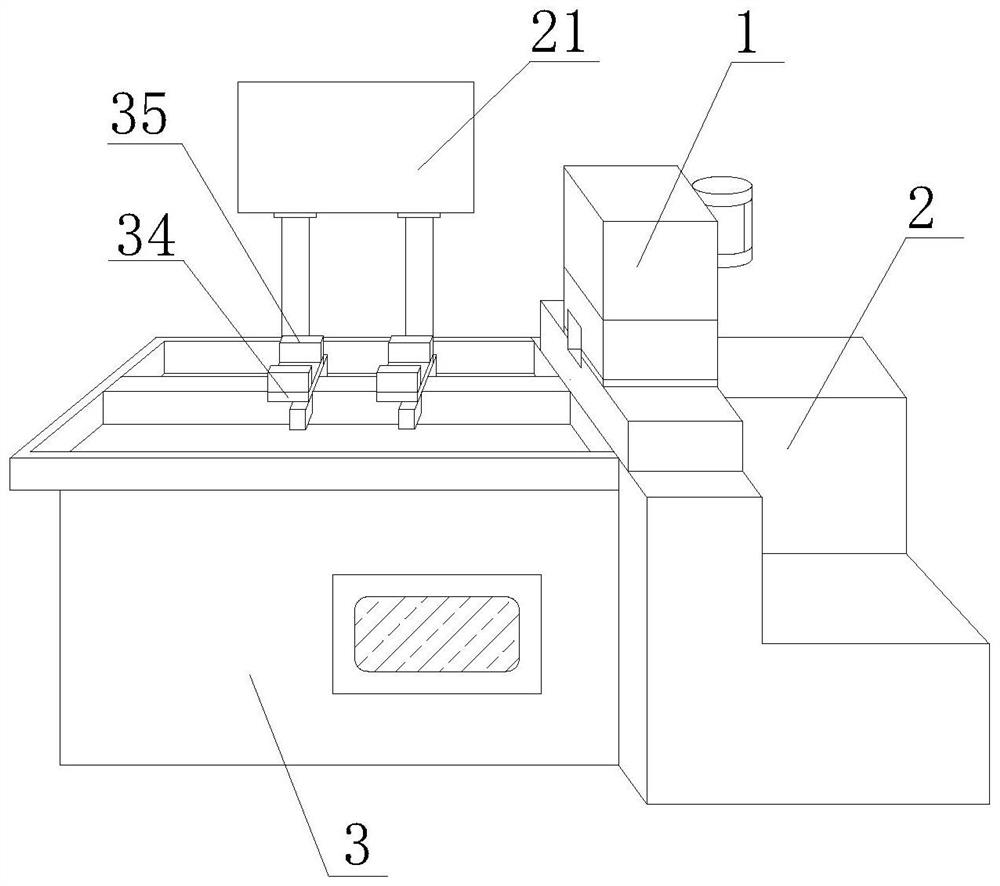
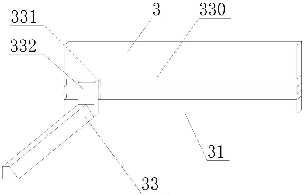
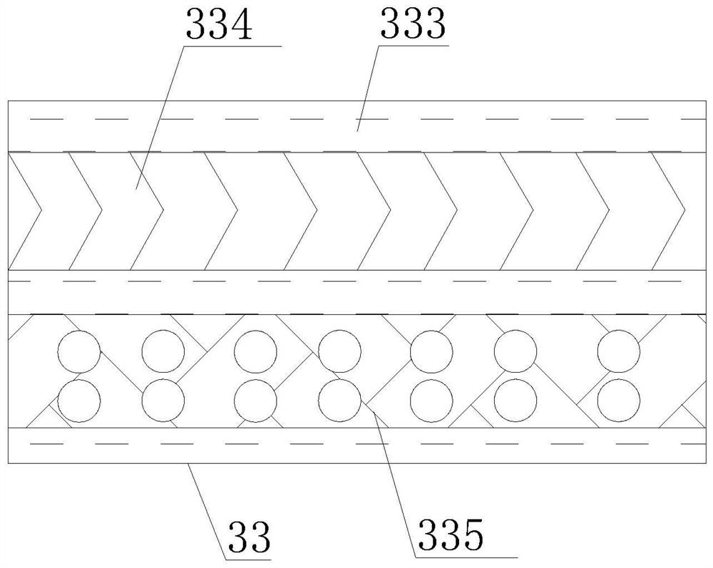
[0037] First aspect, such as Figure 1-9 As shown, the present invention provides an aluminum alloy profile processing tool, including a cutter body 1, a mounting table 2, and a machined stage 3. The bottom portion of the cutter body 1 is fixedly mounted, and the side surface of the mounting table 2 is provided. The processing table 3, the back surface of the processing table 3 is fixedly mounted, and the side surface of the fixing mechanism is provided with the cleaning mechanism 31, the cleaning mechanism 31 includes a moving mechanism 32, and the side surface of the moving mechanism 32 is fixedly mounted, and the cleaning plate 33, the cleaning plate 33 The bottom portion is provided with a friction pad 333, and the bottom of the friction pad 333 is provided with a buffer groove, and the internal activity of the buffer groove is attached, and the bottom portion of the connecting post 3343 is provided with a scraping block 334, and the side surface of the blade 334 is fixedly mou...

Embodiment 2

[0040] Such as Figure 1-9 As shown in the basis of the first embodiment, the present invention provides a technical solution: preferably, the inside of the connecting post 3343 is fixedly mounted with a fixing plate 3344, and two sides of the surface of the fixing plate 3344 are provided with a slide 3345, a slide 3345. The internal activity is attached to the other end of the hydraulic rod 3346, and the other end of the chute 3345 is fixedly mounted, and the inner side of the fixed ring 3346 is provided with a press block 3347, and one end of the hydraulic rod 3346 is attached to the surface of the fixing plate 3344, hydraulic rod 3346 The other end is provided with a moving block, and the side of the moving block is disposed on the side of the pressing block 3347.

[0041] In the present embodiment, by the connection post 3343 to the fixing ring 3346, the hydraulic rod 3346 is telescopically, thereby driving the moving block inside the slide 3345, pushing the pressing block 3347...

Embodiment 3

[0043] Second, if Figure 1-9 As shown, the present invention also provides a clamping mechanism of an aluminum alloy profile processing tool, and the clamping mechanism of the aluminum alloy profile processing tool is disposed on the machining stage, and the top portion of the processing stage 3 is fixedly mounted with a fixing plate 34, fixed The top portion of the plate 34 is fixedly mounted having a clamping plate 35, and the bottom fixing of the clamping plate 35 is fixedly connected, and the side surface of the telescopic column 351 is provided with a telescopic block 352, and the inner side of the clamping plate 35 is fixedly mounted having a clamp pad 353. The bottom portion of the clamp pad 353 is fixedly mounted, and the bottom portion of the fixed block 354 is provided with a cushion pad 355. The side surface of the cushion 355 is fixedly mounted, and the retractable rod 3551, and the other side of the telescopic rod 3551 is fixed in the clamping plate. On the inside of ...


PUM


Abstract

The invention discloses an aluminum alloy profile machining tool and a clamping mechanism thereof, and relates to the technical field of machining device.The aluminum alloy profile machining tool comprises a cutter body, a mounting table and a machining table, the mounting table is fixedly mounted at the bottom of the cutter body, the machining table is arranged on the side face of the mounting table, and a control panel is fixedly mounted on the back face of the machining table; a cleaning mechanism is arranged on the side face of the fixing mechanism. A moving block and a sliding rail are matched to move, so that a connecting plate and a cleaning plate are driven to move, then the cleaning plate drives a scraping block and an adsorption pad to move, and in cooperation with friction force of the scraping block, the scraping block pushes and scrapes chippings on the surface of a machining table into a cleaning opening to be collected, and then the chippings on the surface of the machining table are removed through adsorbability of the adsorption pad. And the problems that the scraps are prone to remaining on the surface of the device, the scraps fall on a machining table, and manual cleaning is relatively dangerous are solved, the device can conveniently clean the scraps, and the safety performance of the device is improved.

Description

Technical field [0001] The present invention relates to the technical field of processing apparatus, and more particularly to an aluminum alloy profile processing tooling and its clamping mechanism. Background technique [0002] The aluminum alloy is low, but the strength is relatively high, close or exceeded with high quality steel, good plastic, easy to process, can be made into various profiles, and aluminum alloy profiles are the most widely used non-ferrous metal structural materials in industrial applications, in aviation, Aviation, automobile, mechanical manufacturing, ship, building, decoration and chemical industry have been large, with the rapid development of science and technology and industrial economy in recent years, the demand for aluminum alloy cutting structures is increasing, so that the cutability of aluminum alloy The study also puts deeply. [0003] There is the following issues for the prior art: [0004] 1. When cutting the aluminum alloy profile, the proc...

Claims


Application Information

Patent Timeline
Patent Type & Authority Applications(China)
IPC IPC(8): B23Q3/06B23Q11/00
CPCB23Q3/06B23Q11/0042
Inventor 李文红
Owner 李文红
Learn More