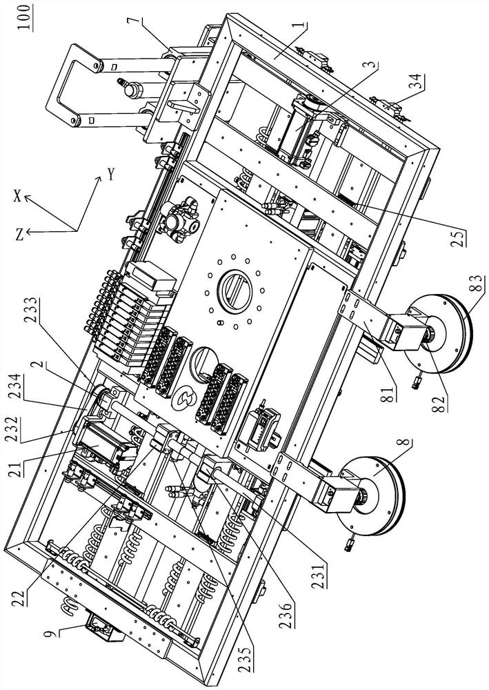
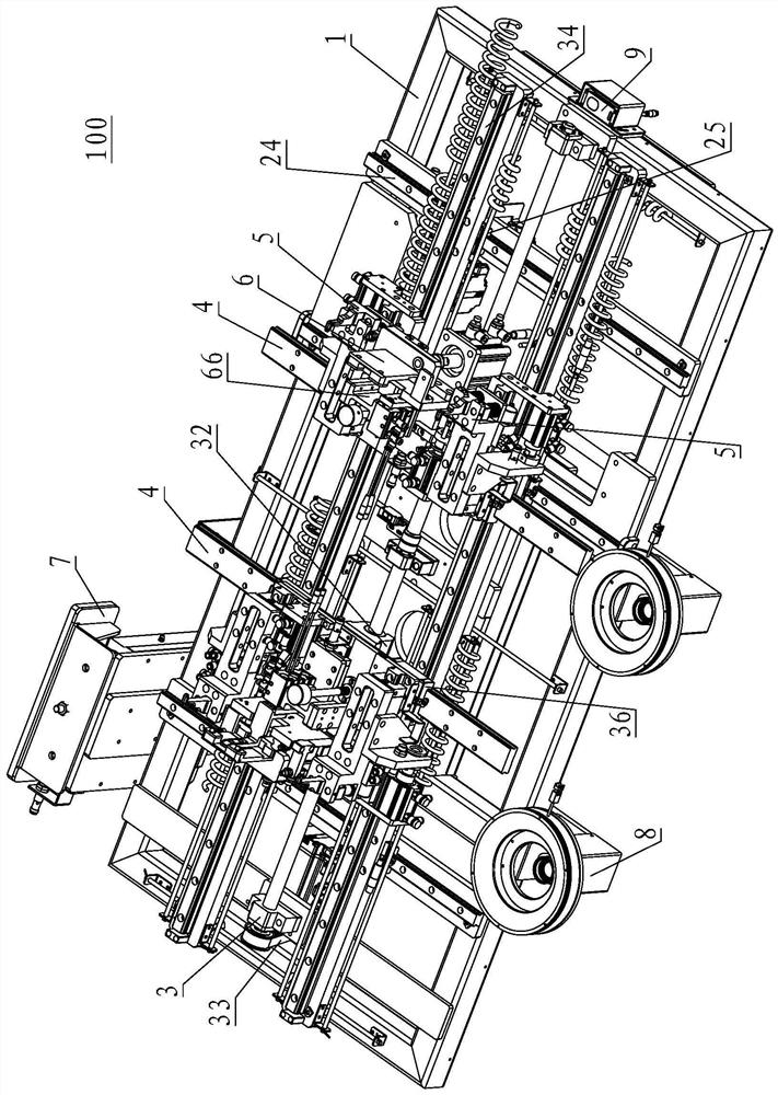
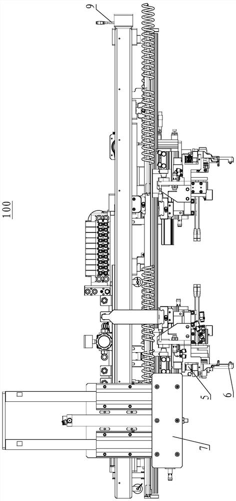
Clamp for square battery module

A prismatic battery and module technology, used in battery assembly, secondary battery manufacturing, chucks, etc., can solve the problems of battery module sliding, battery module falling into the box, wasting time, etc., to avoid falling Effect

Pending Publication Date: 2022-03-11
FUJIAN NEBULA ELECTRONICS CO LTD
View PDF0 Cites 1 Cited by
  • Summary
  • Abstract
  • Description
  • Claims
  • Application Information

AI Technical Summary

Problems solved by technology

[0004] (1) The existing grabbing fixture can usually only judge whether the predetermined placement of the battery module in the box meets the requirements
When the battery module is put into the box, in order to fix the battery module, the position where the battery module is placed in the box is coated with glue in advance, and then the gripper is used to hold the battery module and put it into the predetermined position. It takes time for the glue to solidify, and the glue Easy to slip, after the battery module is put in, it is easy for the battery module to slide on the glue and be misplaced, which will cause the battery module to occupy the position of the surrounding battery modules, resulting in the failure of the adjacent battery modules The placement of adjacent battery modules does not meet the requirements. In the prior art, it is usually waiting for the staff to handle the abnormality, which requires stopping production and waiting, wasting time
[0005] (2) The grabbing fixture of the existing battery module usually grabs the battery module through a set of hooks or grippers on both sides, and the battery module may become loose during the moving process
Due to manufacturing and assembly errors, there are differences in the thickness H1 of the battery module, and the thickness H1 of some battery modules may be larger or smaller than the battery module used for debugging and setting programs.
If it is smaller, it will appear at the coordinate Z1, the battery module is suspended, at this time, work according to the predetermined program, grab the clamp to release the battery module, then the battery module will fall into the box, and it is easy to remove the battery module. The battery module is broken, and the battery module is charged, which is likely to cause safety hazards

Method used


Image

  • Clamp for square battery module
  • Clamp for square battery module
  • Clamp for square battery module

Examples


Embodiment Construction

[0093] In the description of the present invention, it should be understood that the description indicating the orientation or positional relationship is based on the orientation or positional relationship shown in the drawings, which is only for the convenience of describing the present invention and simplifying the description, rather than indicating or implying the Devices or elements must have a specific orientation, be constructed and operate in a specific orientation, and therefore should not be construed as limiting the scope of the invention.

[0094] In the description of the present invention, it should be noted that, unless otherwise clearly specified and limited, the terms "arrangement", "connection" and "connection" should be understood in a broad sense, for example, it can be a fixed connection or a detachable connection. Connected, or integrally connected; it can be mechanically connected or electrically connected; it can be directly connected or indirectly conne...


PUM


Abstract

The invention provides a clamp for a square battery module. The clamp comprises a support frame; an X-axis variable pitch mechanism; a Y-axis variable pitch mechanism; an X-axis switching guide rail; the four first hook claw parts comprise first hook claws floating along the Z axis, the first hook claw parts are movably connected to the X-axis switching guide rails along the X axis, each X-axis switching guide rail is correspondingly connected with two first hook claw parts, and the four first hook claw parts are arranged in a rectangular shape; the two second hook claw parts comprise second hook claws floating along the Z axis, and the second hook claw parts are fixed to the center positions of the X-axis switching guide rails in a one-to-one correspondence mode; the side pushing mechanism is fixed on one side of the supporting frame; a vision unit; and a detection device. Two groups of claws are arranged, double insurance is achieved, and falling is avoided; a side pushing mechanism is arranged, shutdown waiting is not needed, and abnormity can be automatically handled; and each hook claw can float, so that the battery module is ensured to be placed in place, and the phenomenon that the battery module is suspended and falls in place due to errors is avoided.

Description

【Technical field】 [0001] The invention relates to a grabbing device for a square battery module, in particular to a clamp for a square battery module. 【Background technique】 [0002] Following the rise of the country's new energy and vigorously supporting the development, the automotive power battery manufacturing industry will also develop rapidly. The automotive power battery manufacturing industry urgently needs to break through the bottleneck of production capacity improvement and product quality and safety control. [0003] In the process of putting the square battery module into the box, in order to improve efficiency and ensure safety, the battery module is usually clamped by grabbing fixtures, and then the battery module is put into the box. However, the existing grabbing fixtures have the following disadvantages: [0004] (1) The existing gripping fixtures can usually only judge whether the predetermined placement of the battery module in the box meets the requirem...

Claims


Application Information

Patent Timeline
Patent Type & Authority Applications(China)
IPC IPC(8): B25J15/08B25J5/02H01M10/04
CPCB25J15/08B25J5/02H01M10/0404Y02P70/50
Inventor 刘作斌刘永吴锦宇
Owner FUJIAN NEBULA ELECTRONICS CO LTD
Why Eureka
Try Eureka