
Eureka
For R&D, Eureka makes reading and utilizing patents & technical documents easy.
Eureka AIR
Designed for self-driven R&D workflows. Generate viable solutions, solve complex R&D challenges, empower your innovation with AI.

Eureka Materials
Designed for material experts only. Revolutionize your material R&D, from search, analyze, to developing new materials.

TechResearch
Generate reliable direction feasibility study reports for your R&D in just a few steps.

TechSeek
Discover and master advanced knowledge NOW. Basics, ideas, possibilities, all at once.

TechMind
As an expert in R&D Theories, TechMind can generates customized viable solutions instantly.

TechRisk
Analyze your overall solution with one click, know your potential R&D risks in advance.

TechMonitor
Get weekly tech updates, stay abreast of the latest tech innovations and key insights.
Concrete on-site pumping vacuum stirring conveying pipe and construction technology
A vacuum mixing and concrete technology, which is applied to cement mixing devices, clay preparation devices, unloading devices, etc., can solve the problem of uncontrollable air content and achieve a high degree of controllable air content
- Summary
- Abstract
- Description
- Claims
- Application Information
AI Technical Summary
Problems solved by technology
Method used
Image

Examples
Embodiment 1
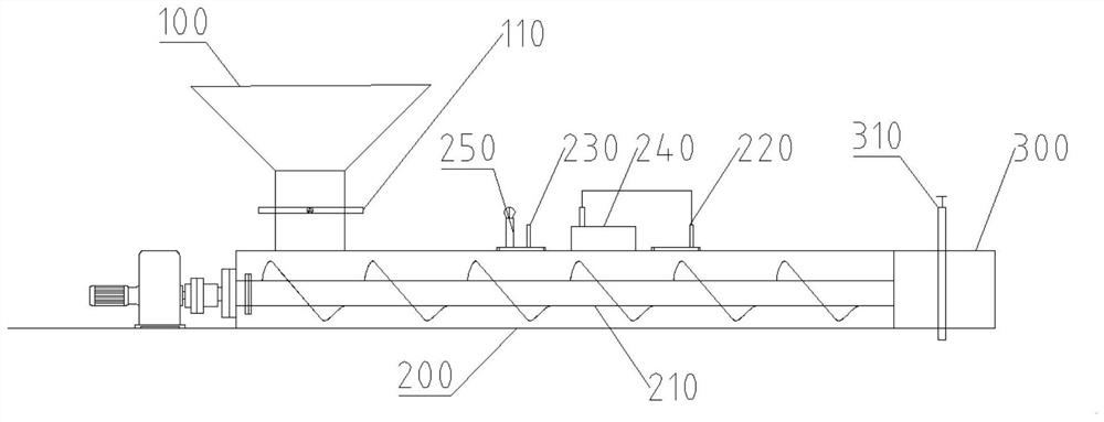
[0044] Such as figure 1 As shown, a vacuum mixing conveying pipe for concrete on-site pumping includes a feed hopper 100 and a pipe body 200 outlet 300. The feed hopper 100 is connected to the pipe body 200, and the feed hopper 100 is used to supply 200 into concrete; the discharge port 300 communicates with the end of the pipe body 200 away from the feeding place, and the discharge port 300 is used to discharge the concrete in the pipe body 200; the feed hopper 100 is provided with a feed valve 110, The material valve 110 is used to close and air-seal the channel between the feed hopper 100 and the pipe body 200; the discharge port 300 is provided with a discharge valve 310, and the discharge valve 310 is used to close and air-seal the discharge port 300 and the pipe body. The channel between the bodies 200; the two ends of the pipeline are sealed by valves to form an airtight environment, which is convenient for the subsequent vacuuming operation.
[0045] The tube body 200...
Embodiment 2
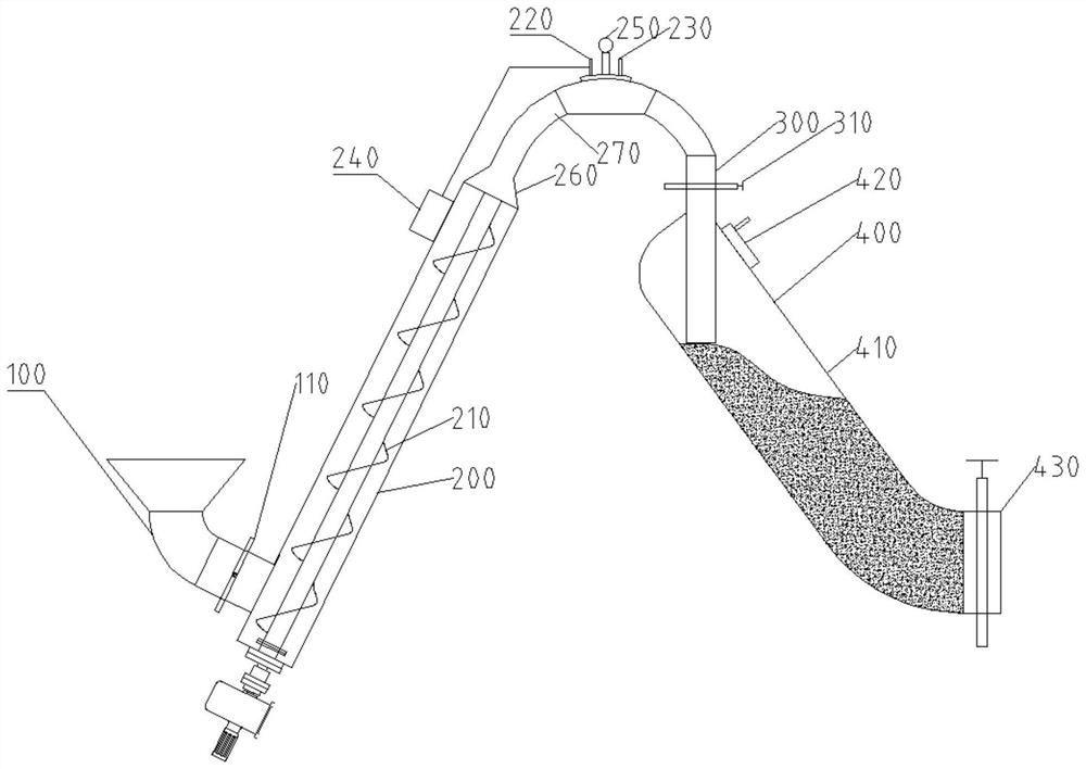
[0050] Such as Figure 2-Figure 5 As shown, if the pipe body 200 is installed horizontally, using a screw feeding device, when the concrete is being stirred, the pressure of the air bubbles wrapped in the concrete itself is higher than the air pressure in the pipe body 200, and they will quickly burst to achieve the purpose of defoaming, but The cost of vacuuming the equipment to a state where there is no air is too high, so there will still be air in the tube body during normal operation. When the concrete is mixed by the screw feeder, the concrete will cover the air in the pipe body 200. Although the air pressure is lower than the outside, there will still be a small amount of air entering the concrete, and this part of the concrete will form a small amount of air after entering the air. bubble. Therefore, in order to reduce or avoid the re-entry of air after defoaming, the equipment should be improved.
[0051] The axis of the pipe body 200 forms an included angle of 45-9...
Embodiment 3
[0057] Such as Figure 2-Figure 5 As shown, the discharge port 300 communicates with another opening of the exhaust part 270, the discharge port 300 extends downwards, and extends into the discharge tank 400, the discharge tank 400 has an inclined bottom The side wall, the bottom opening of the discharge port 300 is located above the lower side wall of the discharge tank 400, so that the concrete slides down to the bottom of the discharge tank 400 along the lower side wall; the bottom of the discharge tank 400 It has a discharge tank valve 430 which is used to open and close the discharge port of the discharge tank 400 ; The function of the discharge tank 400 is to buffer the concrete on the one hand, so that it is convenient to enter the pumping equipment continuously; The interior can always maintain a high degree of vacuum. On the one hand, further defoaming is carried out. On the other hand, after the concrete enters the discharge tank, the exhaust part and the discharge ...
PUM
 Abstract
Description
Claims
Application Information
 - R&D Engineer
- R&D Manager
- IP Professional
- Industry Leading Data Capabilities
- Powerful AI technology
- Patent DNA Extraction
Browse by: Latest US Patents, China's latest patents, Technical Efficacy Thesaurus, Application Domain, Technology Topic, Popular Technical Reports.
© 2024 PatSnap. All rights reserved.Legal|Privacy policy|Modern Slavery Act Transparency Statement|Sitemap|About US| Contact US: help@patsnap.com