[0031] Embodiments of the present invention will be described in detail below, and examples of the embodiments are illustrated in the drawings, in which the same or similar reference numerals represent the same or similar elements or elements having the same or similar functions. The embodiments described below are illustrative of the invention, and is intended to be construed as limiting the invention.
[0032] In order to better understand the above technical solution, an exemplary embodiment of the present invention will be described in more detail below with reference to the accompanying drawings. While the exemplary embodiments of the present invention are shown in the drawings, it is understood that the present invention can be implemented in various forms and is not intended to be illustrated herein. Instead, these embodiments are provided in order to be more specifically understood, and the scope of the invention can be communicated to those skilled in the art.
[0033] In order to better understand the above technical solution, the above technical scheme will be described in detail below with reference to the drawings and specific embodiments.
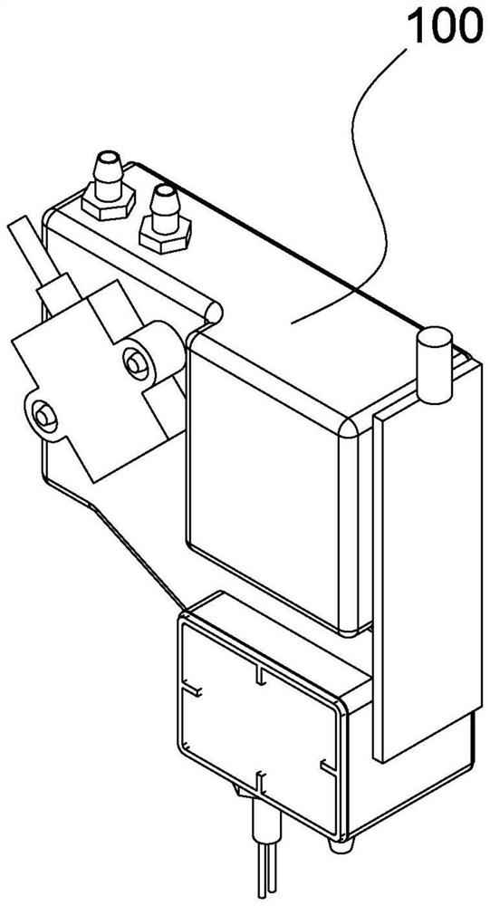
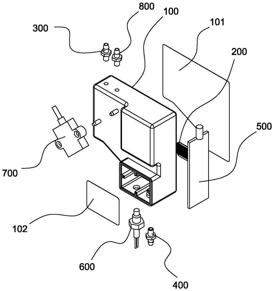
[0034] Such as Figure 1 to 5 As shown, the secondary ink cartridge structure proposed in the embodiment of the present invention includes the ink cartridge body 100 and the filter 200, ink interface 300, an ink interface 400, a heating sheet 500, a temperature sensor 600, and a level 700.
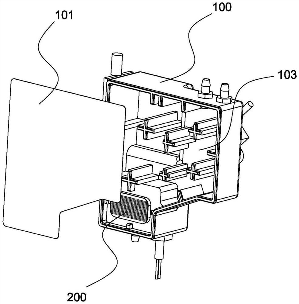
[0035] Wherein, the ink cartridge body 100 is covered with the first cover plate 101 and the second cover plate 102 to form a sealed receiving chamber; the filter 200 is disposed in the receiving cavity of the ink cartridge body 100 to divide the receiving chamber into the first receiving cavity. 103 and the second receiving chamber 104; the ink interface 300 is disposed on the ink cartridge body 100 so that the ink flows into the first receiving chamber 103 through the ink interface 300; the ink interface 400 is disposed on the ink cartridge body 100 to flow ink into the first After the second volume 104, the ink interface 400 is flowed out.
[0036] That is, the receiving cavity in the ink cartridge main body 100 is divided into two by the filter 200, and the ink is ink into the ink cartridge main body by ink interface 300, and then flow into the first receiving chamber 103, and then flow into the second The accommodating chamber 104 is thereby flowing out of the printhead by the ink interface 400 to supply ink ink ink printhead.
[0037] As an embodiment, the ink interface 300 is disposed above the ink cartridge main body 100, that is, one side of the first receiving chamber 103, the ink interface 400 is disposed below the ink cartridge body 100, that is, one side of the second receiving chamber 104; The network 200 is disposed within the ink cartridge body 100 to divide the receiving chamber into the first receiving chamber 103 and the second receiving chamber 104, and the first cover plate 101 is bonded to the ink cartridge main body 100 to limit the first receiving chamber. 103; The second cover plate 102 is bonded to the ink cartridge body 100 to limit the second receiving chamber 104 to greatly fluctuate the pressure of ink ink ink cartridge main body, thereby improving print quality.
[0038] The heating sheet 500 is provided on the ink cartridge body 100 to heat the ink ink cartridge; the temperature sensor 600 is disposed on the ink cartridge body 100 to measure the temperature of the ink ink cartridge.
[0039] It should be noted that when the temperature sensor 600 measures the ink temperature above the preset threshold, the heating sheet 500 stops working; when the temperature sensor 600 measured, the heating sheet 500 starts working.
[0040] It should be noted that the above predetermined threshold is set according to actual needs, or may be 45 °.
[0041] Wherein, the liquid level 700 is disposed on the ink cartridge body 100 to measure the height of the ink in the ink cartridge.
[0042] That is, the amount of ink is controlled by the liquid level 700 in the secondary ink cartridge. When the ink reaches the preset height, the liquid level 700 transmits the control signal to the external ink pump to control the external ink pump to suspend the work, Until the liquid level 700 detects that the ink consumed by the printhead is lower than the predetermined height, the liquid level 700 transmits the control signal to the external ink pump to control the external ink pump to continue working to reinjub into the ink.
[0043] As an embodiment, the liquid level 700 is tilted on the ink cartridge body 100.
[0044] As an embodiment, the liquid level 700 is inclined in a clockwise direction relative to the ink cartridge body 100.
[0045] It should be noted that by inclined the liquid level 700 relative to the ink cartridge body 100, it can measure the ink cartridge when the printhead is vertically downward or horizontally from the right direction or horizontally. The ink height within the main body 100 is heased to increase the sensitivity of the liquid level 700.
[0046] Preferably, the tilt angle range of the liquid level gauge 700 is provided to 45 ° -50 °, thereby further increasing the sensitivity of the liquid level 700.
[0047] As an embodiment, the secondary ink cartridge structure further includes measuring the air pressure port to measure the air pressure in the ink cartridge body by measuring the air pressure port.
[0048] As an embodiment, both the first cover plate 101 and the second cover plate 102 are a PE composite film.
[0049] It should be noted that the PE composite film further reduces the change in ink pressure while making the manufacturing process of the secondary ink cartridge.
[0050] As an embodiment, the filter is 5 μm stainless steel mesh.
[0051]Incidentally, 5 m stainless steel sieve to eliminate air bubbles can be further gentle pressure change of ink, while the removal of impurities may be present in the ink.
[0052] As an example, the ink cartridge main body 100 as a whole L-shaped structure.
[0053] As a particular embodiment, as Figure 1-5 , The ink cartridge main body 100 as a whole L-shaped structure, the ink into the ink interface 300 and interface 400 are provided at both ends of the L-shaped structure; when the ink enters the ink feed from the receiving interface 300 to the first chamber 103 flows into bottom of the first receiving chamber 103, and into the second chamber 104 through the screen 200.
[0054] Incidentally, the print head has a vertical downward vertically or horizontally from right to the left spray jet two modes of operation, the cartridge body 100 is provided by an L-type and the vertical discharge when the ink liquid spray and pour in the ink Interface generating a pressure P = ρgH x Are equal, wherein, H x For the vertical spray and pour water level to a height of the ink jet ink interface, ρ is the specific gravity of the ink, g is the gravitational acceleration.
[0055] As described above, according to the proposed structure of the two ink cartridges of the present invention, includes a cartridge body, the filter, the ink feed port, the ink interfaces, a heating plate, a temperature sensor and a level gauge, a first ink cartridge main body lid closed lid and a second cover plate to form a sealed receiving chamber; filter cartridge receiving cavity disposed at the main body to the receiving area into a first chamber and a second chamber receiving receiving chamber; an ink feed interfaces disposed on the ink cartridge main body, so that ink flows through the ink inlet interface of the first receiving chamber; the interface after the ink cartridge is provided on the main body, so that ink flows into the ink chamber through the second receiving interfaces effluent; heating the sheet body disposed on the ink cartridge to the ink cartridge heating the ink; a temperature sensor disposed in the cartridge body, to measure the temperature of the ink in the ink cartridge; gauge disposed on the cartridge body, to measure the height of the ink in the ink cartridge; Accordingly, the ink cartridge main body can be greatly gentle ink pressure fluctuations, thereby improving print quality.
[0056] Further, embodiments of the present invention also provides a printing apparatus which includes the above two container structure.
[0057] In summary, the proposed printing apparatus according to the present invention, the above-described structure of two cartridges, the cartridge body can be greatly gentle pressure fluctuations in the ink, thereby improving the print quality.
[0058] In the description of the present invention, it is to be understood that the terms "center", "longitudinal", "horizontal", "length", "width", "thickness", "upper", "under", "front", " After "," left "," right "," vertical "," horizontal "," top "," bottom "," outside "," clockwise "," counterclockwise "or position The relationship is based on the orientation or positional relationship shown in the drawings, is merely intended to facilitate the description of the present invention and simplified description, rather than indicating or implying that the device or component must have a specific orientation, and operates and operates in a specific orientation, so It is not understood to limit the limitations of the invention.
[0059] Moreover, the term "first", "second" is used only for the purpose of describing, and cannot be understood as an indication or implies a relative importance or implicitting the number of indicated techniques. Thus, features with "first", "second" may be indicated or implicitly including one or more of this feature. In the description of the invention, the meaning of "multiple" is two or more, unless otherwise specifically defined.
[0060] In the present invention, unless otherwise expressly specified or limited, the terms "mounted," "connected," "connected," "fixed" and like terms are to be broadly understood, for example, may be a fixed connection, the connection may be detachable , or integral; may be a mechanical connector may be electrically connected; may be directly connected, can also be connected indirectly through intervening structures, it may be interaction between the two internal communicating elements or two elements. The specific meaning of the above terms in the present invention can be understood in terms of specific cases.
[0061] In the present invention, unless otherwise expressly specified or limited, the first feature in the "on" a second or the "lower" may include direct contact with the first and second features may also comprise a first and a second feature but not in direct contact with the contact by additional features therebetween. Moreover, the first feature "above", "above" and "upper" include the first feature to the second feature is directly above and obliquely, or only means that the first feature level is higher than the second feature. The first feature is in the second feature "under", "below" and "below" include the first feature to the second feature is below and obliquely, or only the first feature level height is less than the second feature.
[0062] In the description of this specification, the description of the reference terms "one embodiment", "some embodiments", "example", "specific example", or "some example", etc., meant to conjunction with the specific characteristics described in connection with this embodiment. , Structures, materials or features are included in at least one embodiment or example of the present invention. In the present specification, a schematic representation of the above terms should not be construed to be for the same embodiment or exemplary embodiments. Moreover, the specific features, structures, materials or features described may be combined in any one or more embodiments or examples. Moreover, those skilled in the art can engage and combine different embodiments or examples described in this specification.
[0063] Although the embodiments of the present invention have been shown and described above, it is understood that the above-described embodiments are exemplary, and cannot be understood as limiting the invention, and those of ordinary skill in the art can be described above. EXAMPLES Change, modify, replace, and variations.