Sand-discharging submerged pump

A technology for sediment discharge submersible pump and pump body, applied in the direction of pumps, pump devices, pump components, etc., can solve the problems of restricting the renewal and development of submersible pumps, and achieve the effect of normal temperature rise, reduced heat generation, and reduced end face specific pressure.

Inactive Publication Date: 2004-10-06
王庆武
View PDF0 Cites 0 Cited by
  • Summary
  • Abstract
  • Description
  • Claims
  • Application Information

AI Technical Summary

Problems solved by technology

Therefore, the problem of "burning the motor into the motor" of the submersible pump, especially the problem of "burning the motor into the water into the submersible pump" has plagued people for a long time and limited the renewal and development of the submersible pump. Small submersible pump stage for discharging soft sewage

Method used


Image

  • Sand-discharging submerged pump
  • Sand-discharging submerged pump

Examples


Embodiment Construction

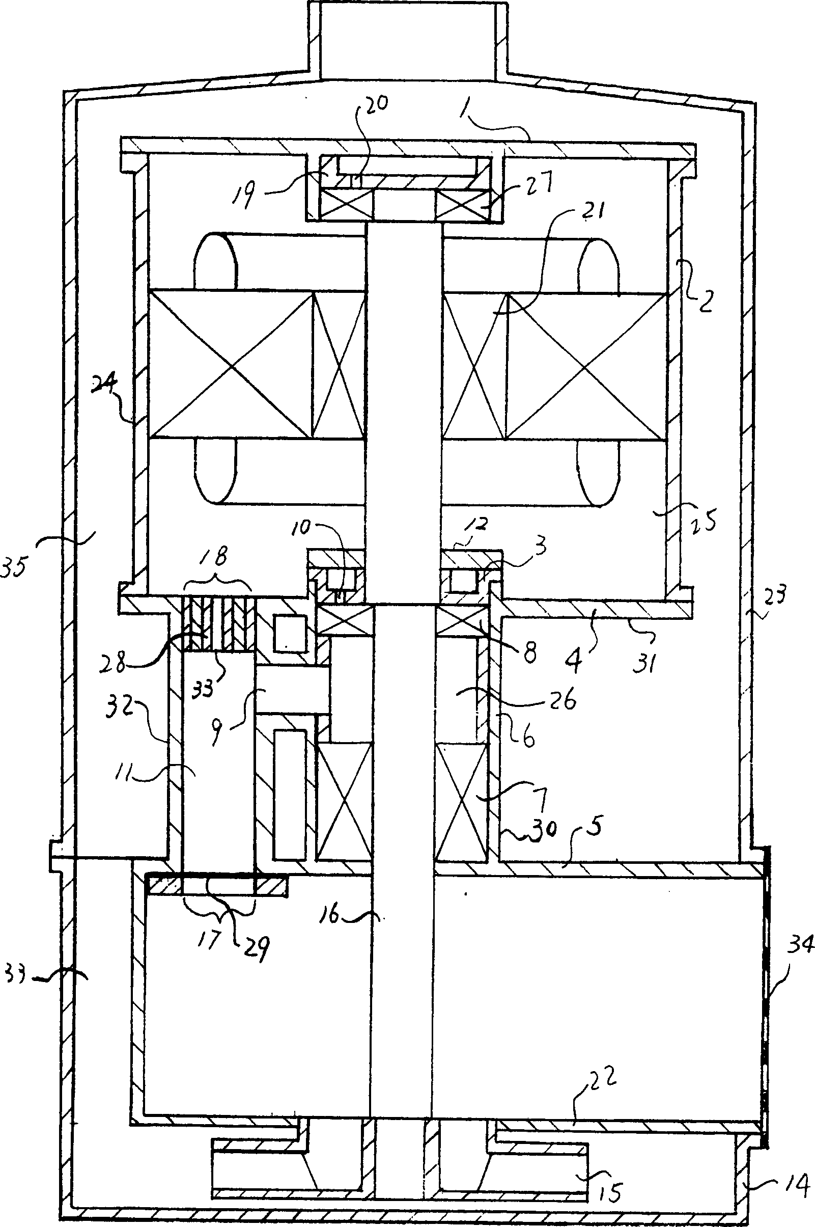
[0011] Attached below figure 1 The present invention is further described.

[0012] figure 1 Among them, the sand discharge submersible pump includes a pump body 14 , a pump shaft 16 , an impeller 15 and a dry motor 24 . Its dry motor 24 is above the pump body 14 . The lower cover plate 5 of the mechanical seal chamber 7 extends to the bottom flange of the casing 23 and supports the filter screen 34 together with the upper cover plate 22 of the pump body 14 and the pump body flange. The suction port of the pump body faces upwards. The pump body outlet pipe 33 is connected to the annular cavity 35 formed by the casing 23 and the motor 24 covered by the motor 24 outside. exist figure 1 Among them, the oil storage tank 19 in the motor upper end cover 1 bearing chamber 27, it is placed on the bearing top in the bearing chamber 27, has an oil drip hole 20 on its bottom. The oil storage tank 3 in the lower end cover 4 bearing chambers 8 is placed above the bearing in the beari...


PUM


Abstract

A sand-discharging submerged pump technically features that a water tank is arranged outside the lower bearing chamber of dry-type motor and an oil tank with oil dropping hole on its bottom is arranged above the bearing. Said water tank has top opening and through hole communicated to cavity between mechanical seal and lower bearing. Said water tank can collect the water come into motor and said oil tank can cool the bearing.

Description

technical field [0001] The invention relates to a sand-discharging submersible pump, in particular to an explosion-proof sand-discharging submersible pump suitable for conveying liquid containing solid abrasives. Background technique [0002] Existing submersible pumps pursue the "absolute" reliability of mechanical seals in order to prevent water from entering the dry motor, and the technical measures taken are only to increase the specific pressure of the end face of the mechanical seal. In dry motors, the heat loss of bearing grease is serious, especially in the bearings on the motor. Therefore, after the pump is turned on, the mechanical seal and bearing will generate a lot of heat first. After the pump is stopped, the submersible pump parked underwater is quickly cooled. Since "absolute" sealing does not exist, relative leakage does exist objectively. Therefore, the increase and decrease of the pressure in the motor chamber caused by the alternating heating and cooli...

Claims


Application Information

Patent Timeline
Patent Type & Authority Patents(China)
IPC IPC(8): F04D13/08F04D13/16F04D29/00
Inventor 王庆武
Owner 王庆武
Why Eureka
Try Eureka