Composite board surface flatness quality detection equipment

A technology for surface flatness and testing equipment, which is used in mechanical roughness/irregularity measurement, measuring device, mechanical measuring device, etc., and can solve problems such as manual manual feeding.

Pending Publication Date: 2022-03-11
朱杏芳
View PDF3 Cites 1 Cited by
  • Summary
  • Abstract
  • Description
  • Claims
  • Application Information

AI Technical Summary

Problems solved by technology

[0004] In order to overcome the disadvantages of the prior art that manual erasing of the lines drawn during detection and manual feeding is required, the technical problem to be solved is: to provide an automatic feeding device capable of automatically erasing the lines drawn during detection. Composite board surface flatness quality inspection equipment that can automatically clamp and loosen composite boards

Method used


Image

  • Composite board surface flatness quality detection equipment
  • Composite board surface flatness quality detection equipment
  • Composite board surface flatness quality detection equipment

Examples


Embodiment 1

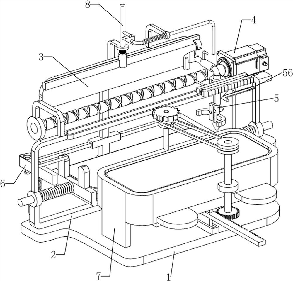
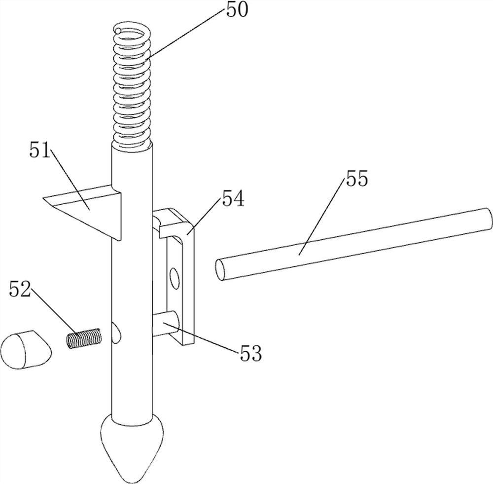
[0072] A composite board surface flatness quality testing equipment, such as figure 1 , figure 2 and Figure 4 As shown, it includes a bottom plate 1, a clamping mechanism 2, a detection mechanism 3 and a lifting mechanism 5, the bottom plate 1 is provided with a clamping mechanism 2, the clamping mechanism 2 is provided with a detection mechanism 3, and the detection mechanism 3 is provided with a lifting mechanism 5.

[0073]When people need to use this device, first people pull the clamping mechanism 2 apart, then place the composite board in the clamping mechanism 2, and then loosen the clamping mechanism 2, so that the clamping mechanism 2 clamps the composite board, In the initial state, the detection mechanism 3 and the lifting mechanism 5 are located above the left side of the bottom plate 1, and then people push the detection mechanism 3 and the lifting mechanism 5 to the right. When the lifting mechanism 5 contacts the composite board, the lifting mechanism 5 dete...

Embodiment 2

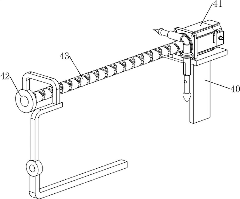
[0079] On the basis of Example 1, such as figure 1 , image 3 , Figure 5 , Figure 6 , Figure 7 and Figure 8 As shown, a moving mechanism 4 is also included. The moving mechanism 4 includes a support plate 40, a servo motor 41, a bearing seat 42 and a twist shaft 43. The right side of the bottom plate 1 is provided with a support plate 40, and the support plate 40 is provided with a servo motor 41. The left side of the slide rail 30 is provided with a bearing seat 42, the bearing seat 42 is provided with a twist shaft 43, the twist shaft 43 is connected with the output shaft of the servo motor 41, and the slide block and the twist shaft 43 are slidably matched.

[0080] After the composite board is placed, the servo motor 41 can be started, and the output shaft of the servo motor 41 drives the twist shaft 43 to rotate, and the twist shaft 43 then drives the slider to move left and right, so that there is no need to manually move the slider. During equipment, close serv...


PUM


Abstract

The invention relates to detection equipment, in particular to composite board surface flatness quality detection equipment. The composite board surface flatness quality detection equipment provided by the invention has the advantages that automatic feeding can be realized, lines drawn during detection can be automatically erased, and the composite board can be automatically clamped and loosened. A composite board surface flatness quality detection device comprises: a bottom plate, which is provided with a clamping mechanism; the detection mechanism is arranged on the clamping mechanism; and the lifting mechanism is arranged on the detection mechanism. According to the invention, the clamping of the composite board is realized through the clamping mechanism, and then under the cooperation of the detection mechanism and the lifting mechanism, the detection of the surface flatness of the composite board is realized.

Description

technical field [0001] The invention relates to a detection device, in particular to a quality detection device for the surface flatness of a composite plate. Background technique [0002] After the production of the composite board is completed, it is usually necessary to carry out a number of quality inspections to determine whether its quality is qualified. One of the more important items is the detection of the surface flatness of the composite board. The existing detection devices are usually large in size. And the structure is complex, and the detection efficiency is high, but when the composite board is inspected, the loading of the composite board is usually done manually, and the lines drawn after the inspection also need to be manually erased, which is more troublesome . [0003] Therefore, there is an urgent need to develop a composite board surface flatness quality inspection device that can automatically load materials, can automatically erase the lines drawn d...

Claims


Application Information

Patent Timeline
Patent Type & Authority Applications(China)
IPC IPC(8): G01B5/28G01B5/00B43L19/00
CPCG01B5/28G01B5/0002G01B5/0004B43L19/00
Inventor 朱杏芳
Owner 朱杏芳
Why Eureka
Try Eureka