Flatness detection device for engineering supervision and use method thereof
A detection device and flatness technology, applied in the direction of mechanical roughness/irregularity measurement, etc., can solve the problems of inaccurate detection results, small detection range, inconvenient inspection, etc., to increase detection range and high safety factor , to ensure the effect of accuracy
- Summary
- Abstract
- Description
- Claims
- Application Information
AI Technical Summary
Problems solved by technology
Method used
Image
Examples
Embodiment 1
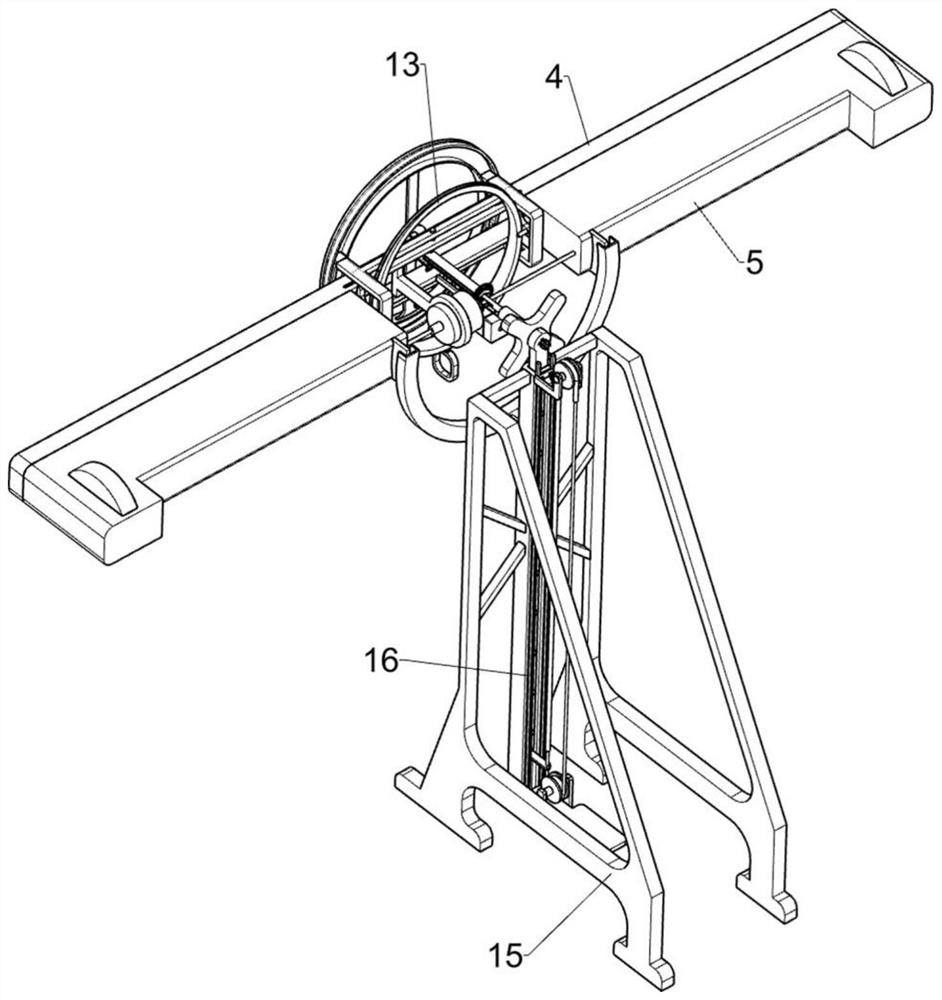
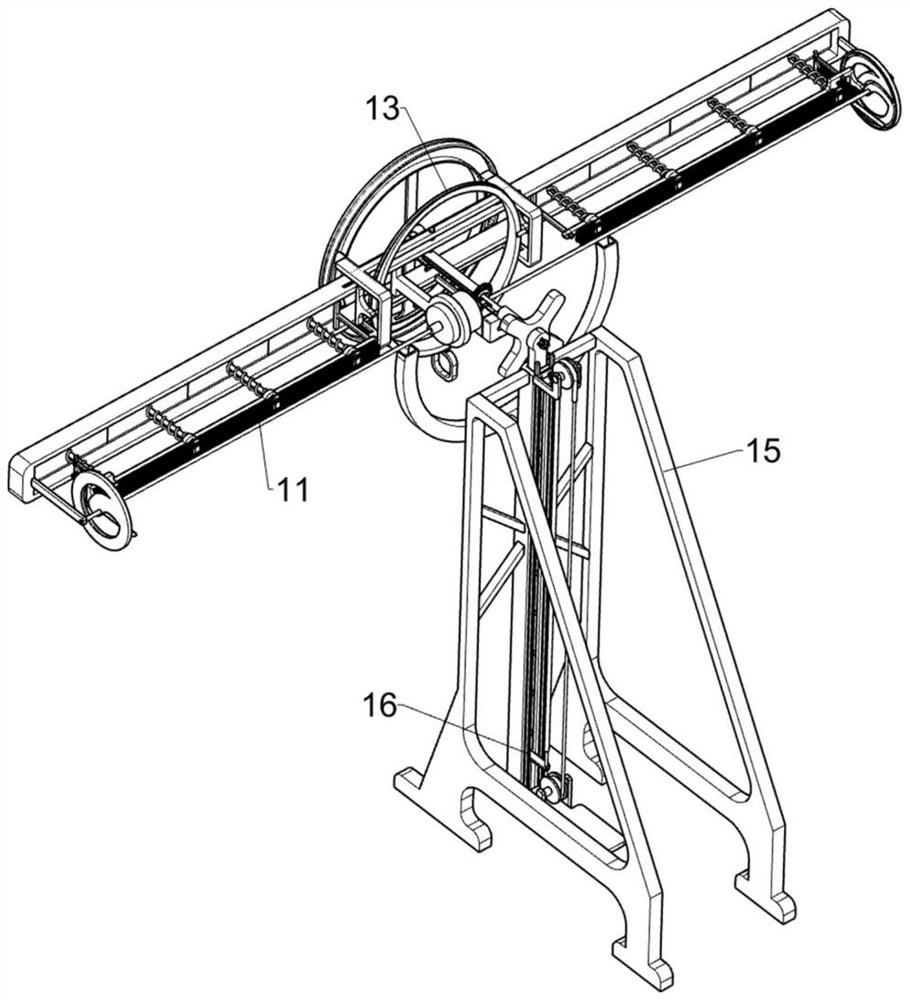
[0064] A flatness detection device for engineering supervision and its use method, such as figure 1 , figure 2 , image 3 , Figure 4 , Figure 5 , Figure 6 , Figure 7 , Figure 8 , Figure 9 , Figure 10 and Figure 11 As shown, it includes a detection ring 1, a first slider 2, a turret 3, a swing frame 4, an outer frame 5, a second slider 6, a return spring 7, a first rotating rod 8, a cross handle 9, and a two-way motor 10. The detection mechanism 11 and the reading mechanism 12. The front side of the detection ring 1 is connected with the first slider 2 in a symmetrical sliding manner. The first slider 2 is in an arc-shaped structure, and a turret is fixedly connected between the two first sliders 2. 3. The middle part of the turret 3 is movably connected with a swing frame 4, and the front side of the swing frame 4 is symmetrically fixed with an outer frame 5, and a pair of second sliders 6 are symmetrically slidingly connected to the turret 3, and the second ...
Embodiment 2
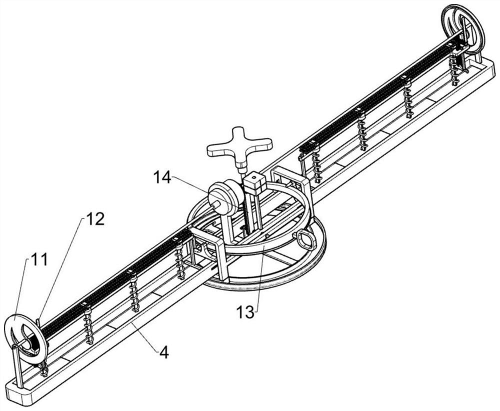
[0069] On the basis of Example 1, such as Figure 12 , Figure 13 and Figure 14 As shown, a leveling mechanism 13 is also included, and the leveling mechanism 13 for swinging frame 4 and its upper device to be placed on the level according to the situation is arranged on the rotating frame 3, and the leveling mechanism 13 includes a fixed ring 131, an oblique ring 132, The first fixed rod 133, the hand push ring 134 and the transparent glass frame 135, the turret 3 is fixedly connected with a fixed ring 131, the fixed ring 131 adopts a ring structure, and the front side of the fixed ring 131 is rotatably connected with a slanted ring 132, and the slanted ring 132 One side is inclined-plane structure, the first fixed rod 133 is symmetrically fixed on the swing frame 4, the first fixed rod 133 is in contact with the front side of the inclined ring 132, the outside of the inclined ring 132 is fixed with a hand push ring 134, and the front side of the swing frame 4 Fixedly conn...
Embodiment 3
[0072] On the basis of Example 2, such as Figure 15 and Figure 16As shown, a rotating mechanism 14 is also included, and the rotating mechanism 14 used for the wide-range detection of the equipment is arranged on the swing frame 4. The rotating mechanism 14 includes a first bevel gear 141, a fixed bar 142, a second fixed rod 143, a second fixed rod 143, Two rotating rods 144, arc bars 145, torsion springs 146 and second bevel gears 147, the first bevel gear 141 is affixed to the output shaft of the bidirectional motor 10 located on the right side, and the front side of the detection ring 1 is symmetrically affixed with fixed bars 142, a pair of second fixed rods 143 are fixedly connected symmetrically on the swing frame 4, and a second rotating rod 144 is connected in rotation on the fixed bar 142, and the second rotating rod 144 contacts with the second fixed rod 143, and one end of the second rotating rod 144 Affixed with arc bar 145, arc bar 145 is arc-shaped, the first ...
PUM
 Abstract
Description
Claims
Application Information
 - R&D
- Intellectual Property
- Life Sciences
- Materials
- Tech Scout
- Unparalleled Data Quality
- Higher Quality Content
- 60% Fewer Hallucinations
Browse by: Latest US Patents, China's latest patents, Technical Efficacy Thesaurus, Application Domain, Technology Topic, Popular Technical Reports.
© 2025 PatSnap. All rights reserved.Legal|Privacy policy|Modern Slavery Act Transparency Statement|Sitemap|About US| Contact US: help@patsnap.com


