Mining optical cable and assembly thereof

A technology of optical cable components and optical cables, which is applied in optical components, light guides, optics, etc., can solve the problems of heavy weight of optical cables used in mining and cannot be paralleled to expand capacity, etc., and achieve the effects of reducing the weight of optical cables, good compressive performance, and large capacity

Pending Publication Date: 2022-03-11
FUTONG GRP JIASHAN COMM TECH CO LTD
View PDF0 Cites 0 Cited by
  • Summary
  • Abstract
  • Description
  • Claims
  • Application Information

AI Technical Summary

Problems solved by technology

[0005] In view of this, the present invention proposes a mining optical cable and its components, which solves the problems in

Method used


Image

  • Mining optical cable and assembly thereof
  • Mining optical cable and assembly thereof
  • Mining optical cable and assembly thereof

Examples


Embodiment 1

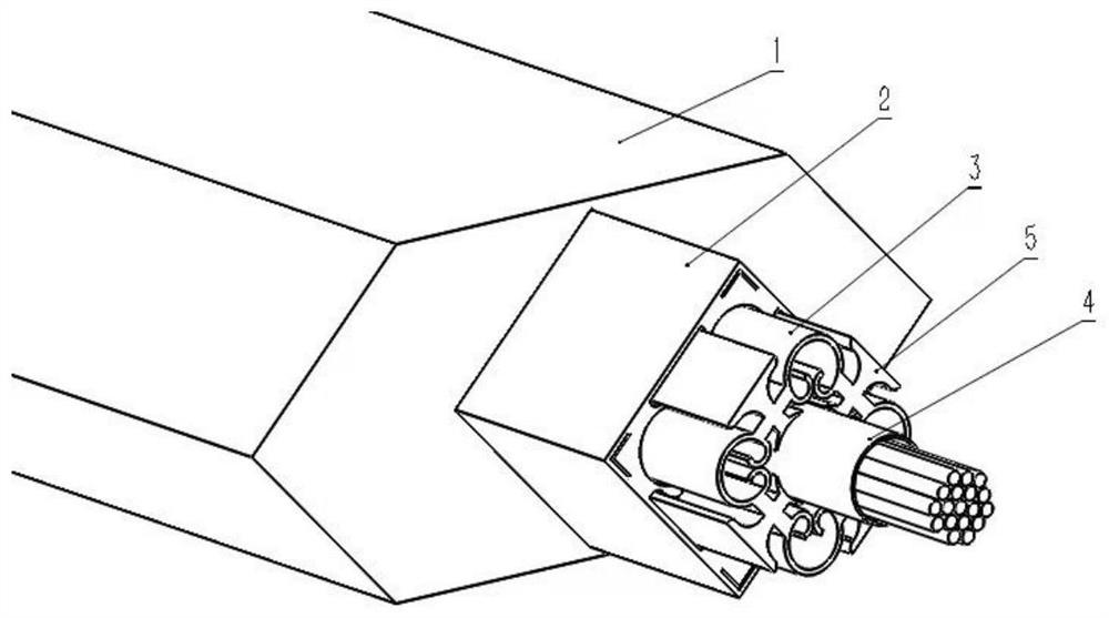
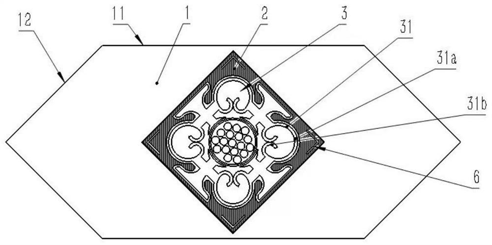
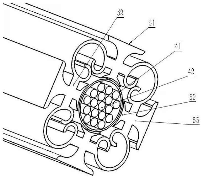
[0039] Such as figure 1 , 2 As shown, a mining optical cable is sequentially provided with a secondary sheath 1, a primary sheath 2, a skeleton 3 and an optical unit 4 from outside to inside.

[0040] The secondary sheath has a hexagonal cross-section and is composed of two parallel long sections 11 of equal length on the upper and lower sides and four short sections 12 of equal length on the left and right sides. Adjacent short sections form a group, and two sets of short sections The sections respectively form two outward-facing vertices in the horizontal direction of the hexagon of the secondary sheath, and the hexagon is symmetrical up and down with the line connecting the horizontal vertices as the line of symmetry.

[0041] The primary sheath is set in the secondary sheath, the cross section is square, the intersection point of the two diagonals of the square is the axis of the optical cable, and the extension of the diagonals of the square passes through two of the sec...

Embodiment 2

[0051] On the basis of embodiment 1, the mine optical cable is further improved, adhesive tape is set on the upper and / or lower side of the mine optical cable in embodiment 1, and the adhesive tape 7 can be passed between two mine optical cables Realize the longitudinal connection to form the longitudinal assembly of the mine optical cable, specifically as Figure 5 shown.

[0052] In addition, at the two horizontal vertices of the secondary sheath of the mine optical cable, an arc slot 8 recessed inward and an arc-shaped plug 9 protruding outward are respectively provided. The above-mentioned mining optical cables are connected horizontally through the cooperation of slots and plugs, such as Figure 6 As shown, the plug of the mine optical cable on the left is adapted to be inserted into the slot of the right mine optical cable, and the plug of the right mine optical cable continues to connect to the new slot to the right, and the two are connected to form a horizontal assem...


PUM


Abstract

The invention discloses a mining optical cable which is sequentially provided with a secondary sheath, a primary sheath, a framework and an optical unit from outside to inside, and the section of the secondary sheath is hexagonal; the primary sheath is arranged in the secondary sheath, and the cross section of the primary sheath is square; the framework is arranged in the primary sheath and comprises four reinforcing hoops and four connecting bands, every two reinforcing hoops are connected through the corresponding connecting band, an axial through hole is formed in the center of the framework, each reinforcing hoop is composed of a long arc section and two identical short arc sections, the long arc sections are in an arc shape arching outwards, and the short arc sections are in an arc shape arching outwards. Each short arc section is in an arc shape arching towards the inner side, the two short arc sections are connected with the two ends of one long arc section respectively, and the two short arc sections abut against the inner side in a back-to-back mode. And the optical unit is one or more optical fibers sleeved in the beam tube, and the optical unit is arranged in the through hole along the axial direction. The mining optical cable is good in compression resistance and light in weight, and doubling and capacity expansion can be carried out on the basis of an original optical cable.

Description

technical field [0001] The invention belongs to the field of optical cables, in particular to a mining optical cable. Background technique [0002] Mining optical cable is a kind of optical cable used in mines such as coal mines, gold mines, and iron mines. In view of the complex environment of mines, the requirements for mine optical cables are relatively high, and they need to meet performance requirements such as rodent resistance, compression resistance, and fire prevention. The current mining optical cables use metal reinforcements as the central support, and thin steel wires or steel belts as the protective layer. Although they meet the requirements of rodent prevention and fire protection, they are heavy, and when the optical cable needs to be expanded, new lines can only be laid. Cannot be merged on the basis of the original line. [0003] In addition, in some lightning-prone mines, metal reinforcements and metal wires or belts will accumulate electric charges to g...

Claims


Application Information

Patent Timeline
IPC IPC(8): G02B6/44
CPCG02B6/443G02B6/4432G02B6/44384
Inventor 王醒东曹雨军
Owner FUTONG GRP JIASHAN COMM TECH CO LTD
Why Eureka
Try Eureka