
Eureka
For R&D, Eureka makes reading and utilizing patents & technical documents easy.
Eureka AIR
Designed for self-driven R&D workflows. Generate viable solutions, solve complex R&D challenges, empower your innovation with AI.

Eureka Materials
Designed for material experts only. Revolutionize your material R&D, from search, analyze, to developing new materials.

TechResearch
Generate reliable direction feasibility study reports for your R&D in just a few steps.

TechSeek
Discover and master advanced knowledge NOW. Basics, ideas, possibilities, all at once.

TechMind
As an expert in R&D Theories, TechMind can generates customized viable solutions instantly.

TechRisk
Analyze your overall solution with one click, know your potential R&D risks in advance.

TechMonitor
Get weekly tech updates, stay abreast of the latest tech innovations and key insights.
High-low voltage complete switch equipment
A switchgear, high-voltage and low-voltage technology, applied in the field of switchgear, can solve the problem of high cost of dust-proof filter bags, and achieve the effect of avoiding electric shock and injury
- Summary
- Abstract
- Description
- Claims
- Application Information
AI Technical Summary
Problems solved by technology
Method used
Image

Examples
Embodiment 1
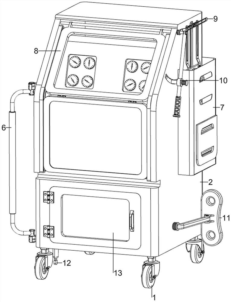
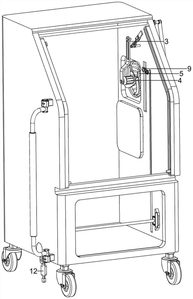
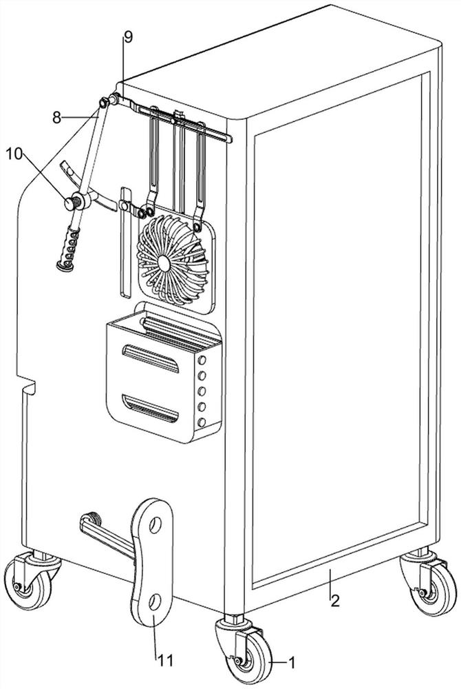
[0038] A high and low voltage complete switchgear, refer to Figure 1-9 , including the first roller 1, the switch cabinet 2, the first fixed frame 3, the servo motor 4, the fan 5, the first armrest frame 6, the protective frame 7, the folding and flipping opening and closing mechanism 8 and the dust removal mechanism 9, the bottom of the switch cabinet 2 The left and right sides are symmetrically rotated forward and backward, and the first roller 1 is provided. The upper part of the right wall of the switch cabinet 2 is provided with a first fixing frame 3. The lower side of the first fixing frame 3 is fixed with a servo motor 4 through bolts. The servo motor 4 outputs A fan 5 is provided on the shaft, a first armrest frame 6 is provided on the left front side of the switch cabinet 2, a protective frame 7 is provided on the upper rear side of the right side of the switch cabinet 2, and a folding and flipping opening and closing mechanism 8 is provided on the front side of the ...
Embodiment 2
[0043] On the basis of embodiment 1, refer to figure 1 and Figure 10 , also includes a locking mechanism 10, the locking mechanism 10 includes a second fixer 101, a bayonet pin 102 and a second tension spring 103, the second armrest frame 82 lower side is provided with a second fixer 101, the second fixer 101 is provided with a bayonet pin 102 slidingly in the middle, and a second tension spring 103 is connected between the right side of the bayonet pin 102 and the second fixer 101 , and two bayonet slots 104 are opened on the upper front side of the right side of the switch cabinet 2 .
[0044] Move the bayonet 102 to the right, the second tension spring 103 is stretched, so that the bayonet 102 is separated from the bayonet groove 104 on the rear side, the second armrest frame 82 rotates, and then drives the second holder 101, the bayonet 102 and the second The tension spring 103 rotates, and when the bayonet 102 is positioned at the right side of the bayonet 104 on the fr...
PUM
 Abstract
Description
Claims
Application Information
 - R&D Engineer
- R&D Manager
- IP Professional
- Industry Leading Data Capabilities
- Powerful AI technology
- Patent DNA Extraction
Browse by: Latest US Patents, China's latest patents, Technical Efficacy Thesaurus, Application Domain, Technology Topic, Popular Technical Reports.
© 2024 PatSnap. All rights reserved.Legal|Privacy policy|Modern Slavery Act Transparency Statement|Sitemap|About US| Contact US: help@patsnap.com