
Device for actuating parking lock in automatic gearbox of motor vehicle

A technology of automatic transmission, control device, applied in the direction of transmission control, mechanical equipment, components with teeth, etc., which can solve the problems of gearbox disengagement, unsafe vehicle state, undesired, etc.

Pending Publication Date: 2022-03-11
KUSTER HLDG
View PDF2 Cites 0 Cited by
  • Summary
  • Abstract
  • Description
  • Claims
  • Application Information

AI Technical Summary

Problems solved by technology

[0007] Furthermore, in the actuator of DE 10 2011 014 815 A1 in order to prestress the spring element, the P position must be disengaged, resulting in an undesired and unsafe vehicle state, since even if the emergency mechanism is not yet available, The P position of the transmission will still disengage

Method used


Image

  • Device for actuating parking lock in automatic gearbox of motor vehicle
  • Device for actuating parking lock in automatic gearbox of motor vehicle
  • Device for actuating parking lock in automatic gearbox of motor vehicle

Examples


Embodiment Construction

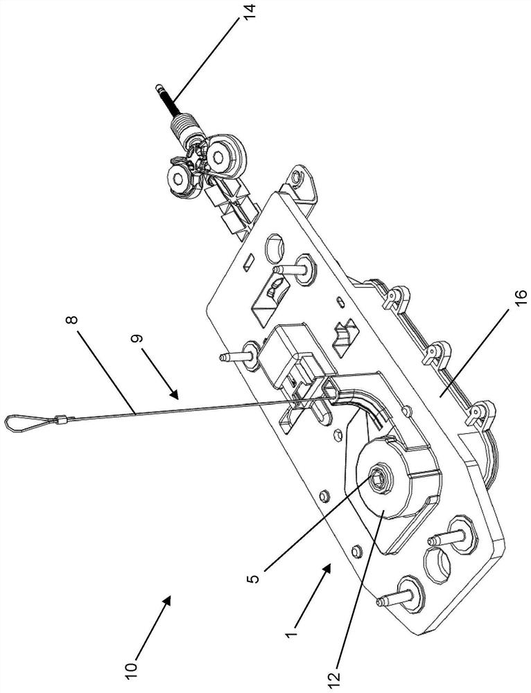
[0052] figure 1 An exemplary embodiment of a device 10 according to the invention arranged in a housing 16 for actuating a parking lock mechanism in an automatic transmission of a motor vehicle with a device known from the prior art is shown. An actuator for adjusting the different switching positions of an automatic gearbox of a motor vehicle. In this view can be seen the part of the cable drive 9 with the cable 8 for actuating the device 10 according to the invention, so that the parking lock mechanism in the automatic transmission of a motor vehicle can The operating device 1 is deactivated or activated.

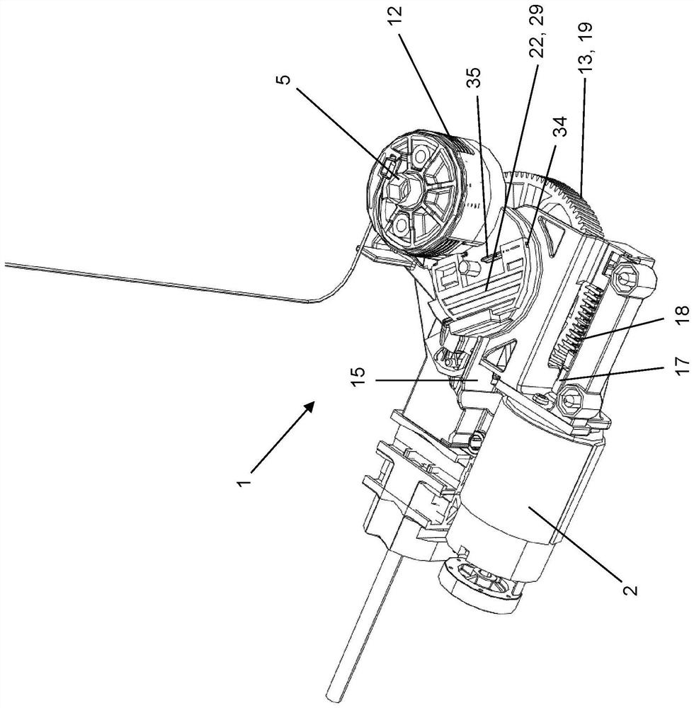
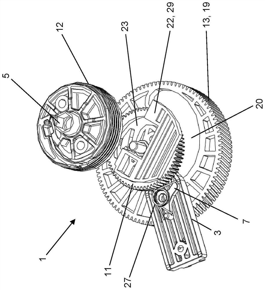
[0053] Depend on figure 2 , 3 and 4 learn how the actuator works. In the illustration, the actuator is here in a position that corresponds to the position of the P position of the automatic transmission of the motor vehicle and thus to a defined angle of the rotary element 19 designed as a gear wheel 13 Location.

[0054] as by image 3 and 4 As is known, a counte...


PUM


Abstract

The invention relates to a device for actuating a parking lock mechanism in an automatic gearbox of a motor vehicle, at least one driving gear, neutral gear and parking gear can be specified by means of a gear selection device, and the parking lock mechanism can be actuated as the parking gear is entered. A parking lock operatively connected to the automatic gearbox can be activated and can be activated or deactivated by an emergency actuation device to be manually actuated. The emergency actuation device has a gear which can be engaged with a spur gear which is designed as an intermediate gear. According to the invention, the first engagement element engages with a control curve provided on the spur gear and can be moved in the control curve during movement of the spur gear in order to activate and deactivate the parking lock.

Description

technical field [0001] The invention relates to a device for actuating a parking lock mechanism in an automatic transmission of a motor vehicle according to the preamble of claim 1 and to a machine according to claim 14 equipped with the device. train. Background technique [0002] In modern motor vehicles, the position of the automatic transmission desired by the driver is usually no longer transmitted by the mechanical coupling of the gear lever to the position controller on the transmission side, but by the automatic gearshift operating device or Shift-by-Wire (shift-by-wire) system transfer. The gear desired by the driver is converted into an electrical signal and transmitted via the control unit to the automatic transmission, which is then adjusted to the desired position ("N", "P", "R", ...) . [0003] The use of automatic gearshifts or shift-by-wire systems in motor vehicles offers several advantages over mechanically coupled gearshifts. In this way, for example, ...

Claims


Application Information

Patent Timeline
IPC IPC(8): F16H63/34
CPCF16H63/3408F16H63/3458F16H63/3416F16H63/3491F16H63/3425
Inventor M·布吕歇尔T·施密特
Owner KUSTER HLDG
Learn More