Unconventional steel plate wafer cutting device and implementation method thereof

An unconventional, steel plate technology, applied in the field of stamping, can solve problems such as material waste, achieve the effects of improving processing efficiency, fast blanking, and improving utilization

Active Publication Date: 2022-03-15
HENGDIAN GRP DMEGC MAGNETICS CO LTD
View PDF6 Cites 0 Cited by
  • Summary
  • Abstract
  • Description
  • Claims
  • Application Information

AI Technical Summary

Problems solved by technology

However, there is a waste of material when using regular wafers to stretch the double-flat casing products

Method used


Image

  • Unconventional steel plate wafer cutting device and implementation method thereof
  • Unconventional steel plate wafer cutting device and implementation method thereof
  • Unconventional steel plate wafer cutting device and implementation method thereof

Examples


Embodiment 1

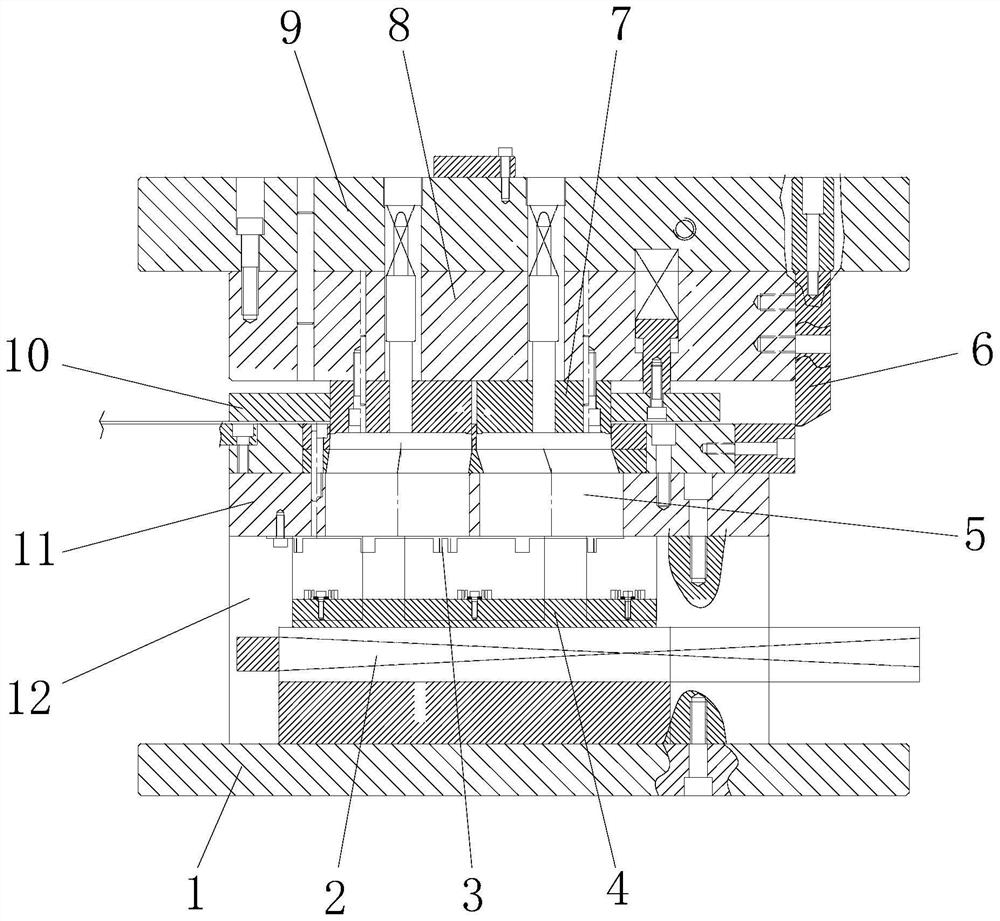
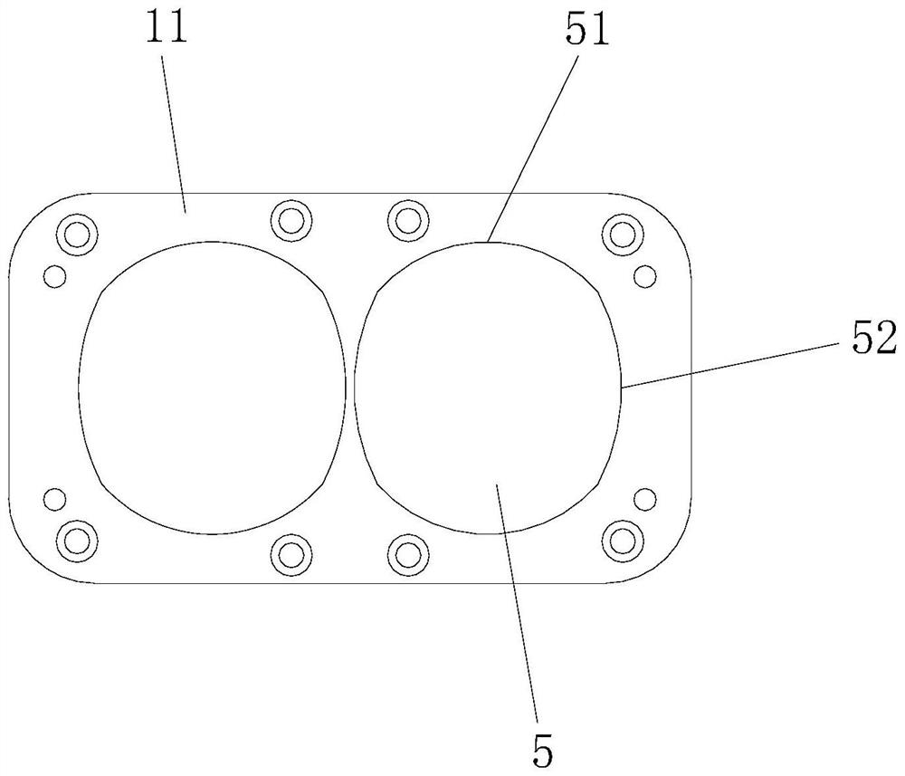
[0038] see Figure 1-8 , the present invention provides the following technical solutions: an unconventional steel plate disc cutting device, comprising a lower fixing seat 1 and an upper fixing seat 9 located above the lower fixing seat 1, a die seat 12 is arranged above the lower fixing seat 1, A die 11 is provided above the die base 12, and two symmetrical cavities 5 are arranged inside the die 11. The die cavity 5 includes two oppositely arranged first arc edges 51 and two oppositely arranged second arc edges. side 52, and the radius of the first arc edge 51 is smaller than the radius of the second arc edge 52, the punch seat 8 is provided below the upper fixed seat 9, and the punch seat 8 is provided with two corresponding to the cavity 5. Punch 7.

[0039] By adopting the above-mentioned technical scheme, the punch 7 and the cavity 5 are designed as a double-flat structure corresponding to the disc product, and the steel plate material with the same area can punch out m...

Embodiment 2

[0045] The difference between this embodiment and Embodiment 1 is that specifically, the inside of the die base 12 is provided with a moving module 2, the moving module 2 is a linear module, purchased from the market, and the output end of the moving module 2 is A mobile platform 4 corresponding to the cavity is provided.

[0046] By adopting the above-mentioned technical solution, the mobile module 2 drives the mobile table 4 to move, so that the punched out double-flat wafer products are delivered to the outside of the mould, and the rapid unloading of the double-flat wafer products is realized.

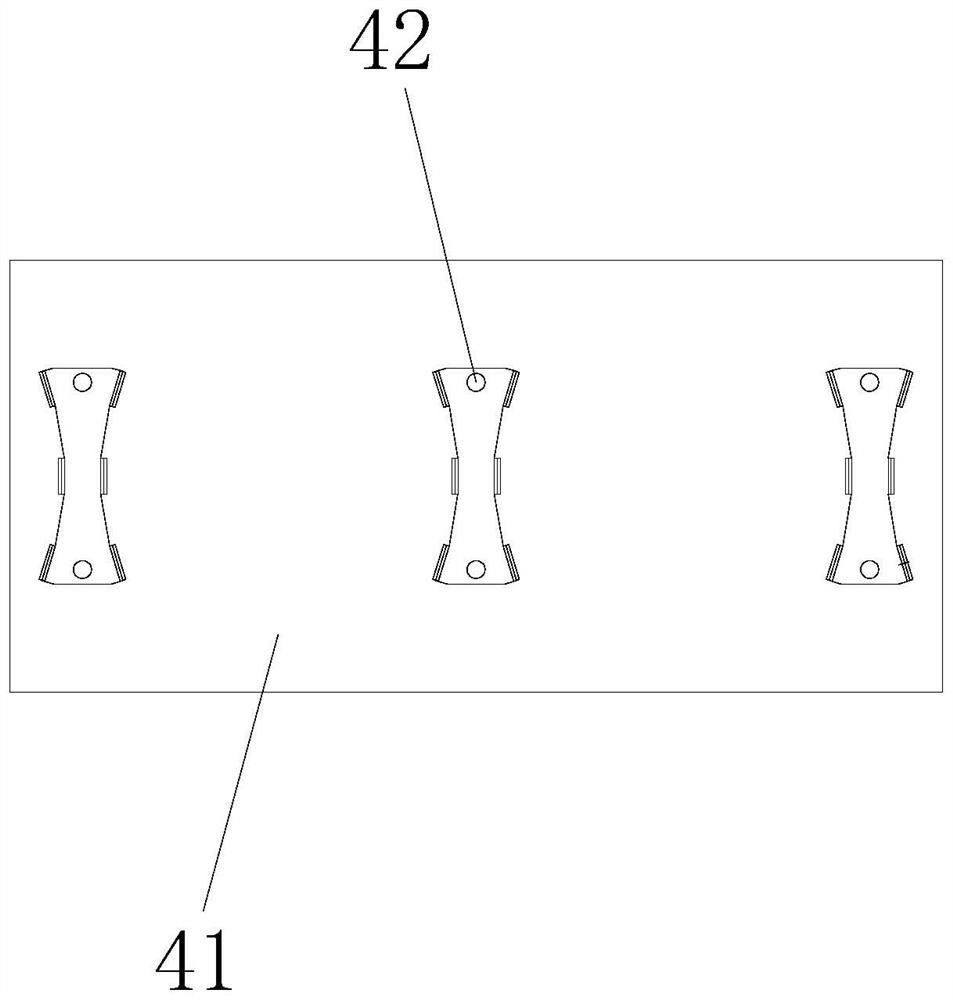
[0047] Specifically, the mobile station 4 includes a base 41, the base 41 is installed on the output end of the mobile module 2, the base 41 is provided with three positioning blocks 42 at equal intervals, the sides of the positioning blocks 42 are arc-shaped structures, and the three positioning blocks Two positioning spaces corresponding to the cavity 5 are formed between the blo...

Embodiment 3

[0050] This embodiment differs from Embodiment 1 in that: specifically, a number of spacers 421 are provided on the side wall of the positioning block 42 , and a slope is provided on the side of the spacer 421 far away from the positioning block 42 .

[0051] By adopting the above technical solution, the positioning of the double-flat wafer product is more precise.


PUM


Abstract

The invention belongs to the technical field of stamping, and discloses an unconventional steel plate wafer cutting device which comprises a lower fixing seat and an upper fixing seat located above the lower fixing seat, a female die seat is arranged above the lower fixing seat, a female die is arranged above the female die seat, two symmetrical cavities are formed in the female die, and the upper fixing seat is located above the upper fixing seat. The cavity comprises a first arc edge and a second arc edge which are oppositely arranged, a male die base is arranged below the upper fixing base, and a male die is arranged below the male die base. The invention further discloses an implementation method of the unconventional steel plate wafer cutting device. The male die and the cavity are designed to be of a double-flat-position structure corresponding to a wafer product, more double-flat-position wafer products can be blanked from a steel plate material with the same area compared with a regular wafer, and therefore the utilization rate of the material is increased; according to the die, the two cavities and the male die are designed, two double-flat-position wafer products can be blanked through one-time action, and therefore the machining efficiency of the double-flat-position wafer products is greatly improved.

Description

technical field [0001] The invention belongs to the technical field of stamping, and in particular relates to an unconventional steel plate disc cutting device and a realization method thereof. Background technique [0002] Miniature vibration motors are indispensable components of electronic products such as mobile phones, tablet computers, and handheld game consoles, which provide users with tactile feedback. At present, mobile consumer electronics products on the market generally use vibration motors as system feedback components, such as incoming call prompts for mobile phones, vibration feedback for game consoles, and so on. [0003] The first process of deep-drawing stamping casing parts is to cut the material discs, and the specifications of the discs are all regular circles. Regular discs can be applied to deep-drawn stamping casings in cylindrical and bi-flat shapes. However, there is a waste of material when using regular wafers to stretch the double-flat casing ...

Claims


Application Information

Patent Timeline
Patent Type & Authority Applications(China)
IPC IPC(8): B21D28/14B21D28/04
CPCB21D28/14B21D28/04
Inventor 叶浩平楼亚晖
Owner HENGDIAN GRP DMEGC MAGNETICS CO LTD
Why Eureka
Try Eureka