
A kind of buttress type high wall steel reinforcement installation and construction system

A buttress-type and steel bar technology, applied in the field of buttress-type high-wall steel bar installation and construction system, can solve the problems of project construction progress, poor safety and reliability, and difficulty in steel bar installation, so as to speed up the overall construction progress, novel and reasonable design, Ease of use for promotion

Active Publication Date: 2022-08-02
SINOHYRDO ENG BUREAU 3 CO LTD
View PDF2 Cites 0 Cited by
  • Summary
  • Abstract
  • Description
  • Claims
  • Application Information

AI Technical Summary

Problems solved by technology

For multiple dry docks with a plane size of 550m×75m, the dock wall of the dry dock is a buttress-type high wall structure with a total height of 13.8m. According to the design requirements, the lower toe wall and the middle vertical wall of the upper structure are removed. One-time construction is required, the installation height of single-layer steel bars is 8.65m, and the center distance between buttress walls is 4.0m; if the conventional scaffolding method is used for construction, the scaffolding will be frequently erected and dismantled, the workload will be heavy, and the construction period will be occupied It takes a long time, requires a lot of labor, and there are many high-altitude operations during the erection period. The safety and reliability are poor, and the working space of the operating platform is narrow due to the small distance between the scaffolding poles, which has a significant impact on the overall construction progress of the project. In addition, the buttress type It is difficult to install the reinforcement one by one in the reinforcement cage of the high wall

Method used


Image

  • A kind of buttress type high wall steel reinforcement installation and construction system
  • A kind of buttress type high wall steel reinforcement installation and construction system
  • A kind of buttress type high wall steel reinforcement installation and construction system

Examples


Embodiment Construction

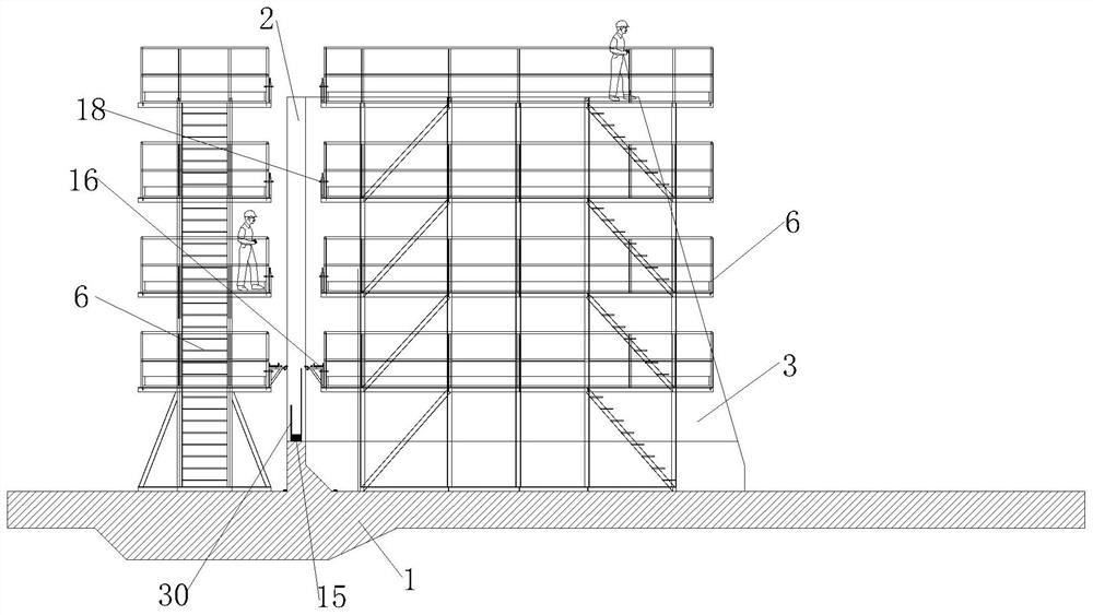
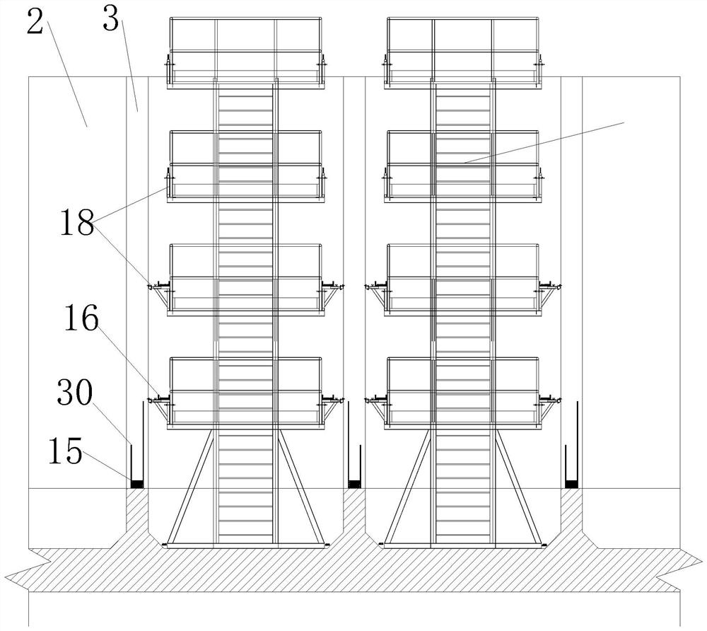
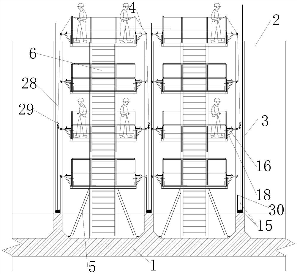
[0035] like Figure 1 to Figure 12 As shown, the present invention includes a buttress-type high-wall steel bar installation and operation platform and a plurality of steel bar tractors 29 for lifting the vertical bars 15;

[0036] The buttress type high wall steel reinforcement installation and operation platform includes N+2 operation sub-platforms 6, one of the N+2 operation sub-platforms 6 is located inside the retaining wall 2, and one of the N+2 operation sub-platforms 6 is located inside the retaining wall 2. N+1 operation sub-platforms 6 are interspersed between the N buttress walls 3 in a spaced manner. The operation sub-platform 6 includes a sub-platform base 5 and a multi-layer single operation layer arranged in sequence from bottom to top. The sub-platform base 5 includes The base plate 7, the single operation layer includes a plurality of interlayer uprights 9 and a layer support frame 10 fixedly arranged on the top of the plurality of interlayer uprights 9, the t...


PUM


Abstract

The invention discloses a buttress-type high-wall steel bar installation and construction system, comprising a buttress-type high-wall steel-bar installation operation platform and a steel tractor; One of the +2 operating sub-platforms is located on the inner side of the retaining wall, and N+1 operating sub-platforms of the N+2 operating sub-platforms are interspersed between the N buttress walls, and N is not A positive integer less than 2; auxiliary parts of the sample rack include auxiliary vertical rods, auxiliary horizontal rods, telescopic rods, sample frame fasteners and spacer columns; rebar pullers include strip steel plates, adjusting screws, butterfly nuts and traction rings. In the present invention, a positioning column for connecting a plurality of sample rack auxiliary parts is arranged on the outer side of the protective fence along the peripheral side of the protective fence. The vertical bars are pulled by the steel tractor, and multiple working surfaces work at the same time without interfering with each other.

Description

technical field [0001] The invention belongs to the technical field of buttress type high wall steel bar installation, and particularly relates to a buttress type high wall steel bar installation and construction system. Background technique [0002] In the reinforced concrete wall structure, especially during the installation and construction of high-rise walls with a single layer, it is often necessary to build scaffolding on both sides of the wall in advance, and then manually install it one by one. For buttress-type high-wall steel reinforcement installation, construction scaffolding needs to be erected on the inside and outside of the retaining wall and between each buttress wall to provide a construction operation platform for operators. For multiple dry docks with a plane size of 550m × 75m, the dry dock wall is a buttressed high wall structure with a total height of 13.8m. According to the design requirements, the lower toe wall and the middle vertical wall of the up...

Claims


Application Information

Patent Timeline
Patent Type & Authority Patents(China)
IPC IPC(8): E04G21/12E04G1/15E04G5/00E04G5/14E02D29/02E04G21/26B63C1/08B63C1/00
CPCE04G21/123E04G1/15E04G5/00E04G5/007E04G5/14E04G5/10E02D29/0275E04G21/26B63C1/08B63C1/00
Inventor 吴刚李东锋雷汉勋孙玉双方涛孟宪坤姚涛孙超李恒
Owner SINOHYRDO ENG BUREAU 3 CO LTD
Learn More