Back pressure valve with flow and pressure control function

A technology of pressure control and back pressure valve, which is applied in the field of hydraulic power system, and can solve the problems of back pressure system air leakage, system failure, and the failure of the sealed steel ball to reset normally.

Pending Publication Date: 2022-03-15
上海极智机电设备有限公司
View PDF0 Cites 0 Cited by
  • Summary
  • Abstract
  • Description
  • Claims
  • Application Information

AI Technical Summary

Problems solved by technology

[0004] When the oil return pressure of the rodless cavity is greater than the elastic force of the spring acting on the sealing steel ball, the back pressure valve opens, and part of the hydraulic oil in the rodless cavity enters the inner cavity of the back pressure valve valve housing through the oil inlet hole, and then passes through the pressure regulating seat. The oil inlet and outlet holes return to the oil tank: but because of the pressure in the rodless chamber of the oil cylinder and the uncertainty of the load, it is not constant. The load is different, and the position of the sealing steel ball of the back pressure valve in the housing is also different. , causing the back pressure to be different, and the oil return flow rate to be unstable
as attached figure 2 As shown, in extreme cases, the back pressure valve spring will be over-compressed and lose its elasticity, causing the sealing steel ball to fail to reset normally, which in turn will cause air leakage in the back pressure system, causing the entire system to fail and fail to work normally.

Method used


Image

  • Back pressure valve with flow and pressure control function
  • Back pressure valve with flow and pressure control function
  • Back pressure valve with flow and pressure control function

Examples


Embodiment

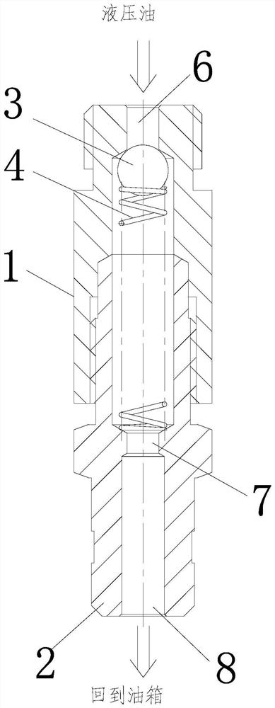
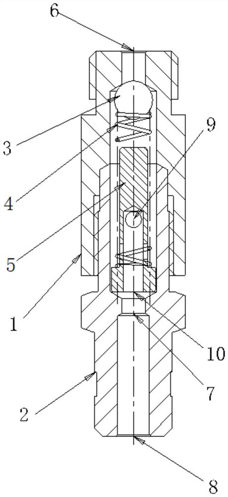
[0029] A back pressure valve with flow and pressure control functions, comprising a valve casing 1 and a pressure regulating seat 2 connected with the valve casing 1, the upper half of the valve casing 1 and the pressure regulating seat 2 are connected on the Together, and in order to ensure that oil does not leak from the gap between the two, a sealing ring is provided at the connection between the valve housing 1 and the pressure regulating seat 2,

[0030] The valve casing 1 is provided with an oil inlet hole 6, and the pressure regulating seat 2 is provided with an oil inlet hole 7 and an oil outlet hole 8, and an inner cavity is formed between the valve casing 1 and the pressure regulating seat 2. The inner cavity is located between the oil inlet hole 6 and the oil inlet hole 7,

[0031] Sealing steel balls 3, springs 4 and spring seats 5 are sequentially arranged in the inner cavity from top to bottom, one end of the spring 4 is nested outside the spring seat 5, and the ...


PUM


Abstract

The invention provides a back pressure valve with a flow and pressure control function, which comprises a valve casing and a pressure regulating seat connected with the valve casing, an oil inlet hole is arranged on the valve casing, an oil inlet hole and an oil outlet hole are arranged on the pressure regulating seat, an inner cavity is formed between the valve casing and the pressure regulating seat, a sealing steel ball, a spring seat and a spring are sequentially arranged in the inner cavity from top to bottom, and the sealing steel ball is connected with the spring seat. One end of the spring is nested outside the spring seat, the other end of the spring is in contact with the sealing steel ball, the bottom end of the spring seat is seamlessly connected with the inner cavity, and a transverse through hole and a longitudinal hole crossed and communicated with the transverse through hole are formed in the spring seat. The spring seat is additionally arranged on the basis of an original back pressure valve, so that the situation that the spring deforms and loses elastic force and fails due to the fact that the spring is compressed infinitely under the limit working state is avoided, and meanwhile the transverse through hole of the spring seat serves as the throttling hole. The oil return flow and pressure of the back pressure valve can be controlled by changing the diameter of the transverse through hole.

Description

technical field [0001] The invention relates to the field of hydraulic power systems, in particular to a back pressure valve with flow and pressure control functions. Background technique [0002] In the two-way hydraulic cylinder, there is a large volume difference between the rod chamber and the rodless chamber. When the cylinder is in the retracted state, the hydraulic oil enters the rod chamber through the hydraulic pump. At this time, the volume of the rod cavity is small, and it will be filled with oil quickly and build up pressure, pushing the cylinder piston to retract. At the same time, the hydraulic oil in the rodless cavity will flow back into the oil tank through the hydraulic control check valve, but at this time The volume in the rodless cavity is large, and the amount of oil is large. If the oil is not returned in time, a large reaction pressure will be generated to offset the thrust of the rod cavity, resulting in slower retraction speed of the oil cylinder. ...

Claims


Application Information

Patent Timeline
Patent Type & Authority Applications(China)
IPC IPC(8): F15B13/02F16K17/04
CPCF15B13/029F16K17/0406
Inventor 秦飞朱金林
Owner 上海极智机电设备有限公司
Why Eureka
Try Eureka