
Pressure regulating type plastic valve

A pressure regulating type and valve technology, applied in the direction of valve details, control valves, valve devices, etc., can solve the problems of valve pipeline damage, economic loss, change of check valve check direction, etc., and achieve the effect of improving the use effect

Inactive Publication Date: 2022-03-15
施漪
View PDF0 Cites 2 Cited by
  • Summary
  • Abstract
  • Description
  • Claims
  • Application Information

AI Technical Summary

Problems solved by technology

[0005] 1. The current valve has a single function when it is used. The throttle valve is the throttle valve, and the check valve is the check valve. When different valves need to be used, it is often troublesome to install multiple valves on the pipeline. At the same time, these current The valve lacks the function of multi-stage pressure relief and pressure regulation. At present, there is a lack of a multi-functional valve that can integrate multiple functions together and can perform different functions according to needs;
[0006] 2. The current check valve can only play the role of a flow direction check when it is used. When the fluid needs to be reversed suddenly, the check valve loses its function at this time, and the direction of the check valve cannot be changed arbitrarily according to the needs of the flow direction. non-return direction;
[0007] 3. If the current valve is in use, if it is suddenly shut down, it will easily cause a water hammer effect to impact the water pipe, which will easily cause damage to the valve and the pipeline, resulting in unnecessary economic losses.

Method used


Image

  • Pressure regulating type plastic valve
  • Pressure regulating type plastic valve
  • Pressure regulating type plastic valve

Examples


Embodiment Construction

[0036] The following will clearly and completely describe the technical solutions in the embodiments of the present invention with reference to the accompanying drawings in the embodiments of the present invention. Obviously, the described embodiments are only some, not all, embodiments of the present invention. Based on the embodiments of the present invention, all other embodiments obtained by persons of ordinary skill in the art without making creative efforts belong to the protection scope of the present invention.

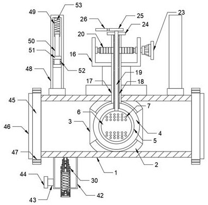
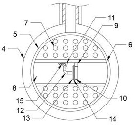
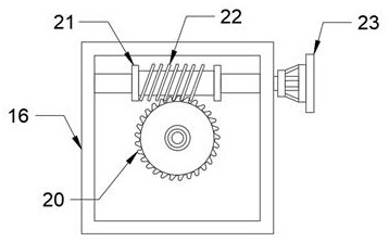
[0037] see Figure 1-12 , the present invention provides a technical solution: a pressure-regulating plastic valve, the valve includes a housing 1, a hollow fixed sphere 2 is fixedly arranged in the middle of the inner side of the housing 1, and both sides of the surface of the hollow fixed sphere 2 are provided with There is a first notch 3, and the inner side of the hollow fixed sphere 2 is provided with a valve function transformation mechanism, and the val...


PUM


Abstract

The invention discloses a pressure regulating type plastic valve which comprises a shell, a hollow fixed ball body is fixedly arranged in the middle of the inner side of the shell, first notches are formed in the two sides of the surface of the hollow fixed ball body, and a valve function conversion mechanism is arranged on the inner side of the hollow fixed ball body. The valve function conversion mechanism comprises a first movable ball body, a second notch, a second movable ball body, a flow channel, a through groove, a baffle, a water through hole, a fixing block, a connecting rod, a valve plate, a first sealing ring and a torsional spring, and the first movable ball body is movably arranged in the middle of the inner side of the hollow fixed ball body in a clamped mode. The ball valve is good in using effect and has a pressure relief adjusting function, the first movable ball body and the hollow fixed ball body form a traditional ball valve to play a role of a stop valve, the second movable ball body is embedded into the first movable ball body, and the valve can be converted into a check valve according to using requirements; meanwhile, the non-return direction of the valve can be changed at will according to needs.

Description

technical field [0001] The invention relates to the field of valves, in particular to a pressure regulating plastic valve. Background technique [0002] Valves are pipeline accessories used to open and close pipelines, control flow direction, adjust and control the parameters (temperature, pressure and flow) of the conveying medium. According to its function, it can be divided into shut-off valve, check valve, regulating valve and so on. [0003] The valve is a control component in the fluid delivery system, which has functions such as cut-off, adjustment, flow diversion, reverse flow prevention, pressure stabilization, flow diversion or overflow pressure relief. Valves used in fluid control systems range from the simplest cut-off valves to various valves used in extremely complex automatic control systems, with a wide variety of varieties and specifications. Valves can be used to control the flow of various types of fluids such as air, water, steam, various corrosive medi...

Claims


Application Information

Patent Timeline
Patent Type & Authority Applications(China)
IPC IPC(8): F16K5/06F16K5/10F16K5/08F16K15/03F16K27/06F16K31/60F16K31/53F16K37/00F16K47/08
CPCF16K5/06F16K5/10F16K5/08F16K15/03F16K27/067F16K31/60F16K31/535F16K37/0025F16K47/08
Inventor 施漪
Owner 施漪
Learn More