Photoelectric tracking image alignment method for anti-sniper robot

A technology of photoelectric tracking and robotics, applied in image analysis, image data processing, instruments, etc., to achieve the effects of improving the automatic alignment accuracy of equipment, improving computing efficiency, and strong authenticity

Pending Publication Date: 2022-03-15
绵阳久强智能装备有限公司
View PDF14 Cites 0 Cited by
  • Summary
  • Abstract
  • Description
  • Claims
  • Application Information

AI Technical Summary

Problems solved by technology

[0003] The purpose of the present invention is to address the above-mentioned deficiencies in the prior art, to provide a photoelectric tracking image alignment method for anti-sniper robots, to solve or improve the above-mentioned problems

Method used


Image

  • Photoelectric tracking image alignment method for anti-sniper robot
  • Photoelectric tracking image alignment method for anti-sniper robot
  • Photoelectric tracking image alignment method for anti-sniper robot

Examples


Embodiment Construction

[0040] The specific embodiments of the present invention are described below so that those skilled in the art can understand the present invention, but it should be clear that the present invention is not limited to the scope of the specific embodiments. For those of ordinary skill in the art, as long as various changes Within the spirit and scope of the present invention defined and determined by the appended claims, these changes are obvious, and all inventions and creations using the concept of the present invention are included in the protection list.

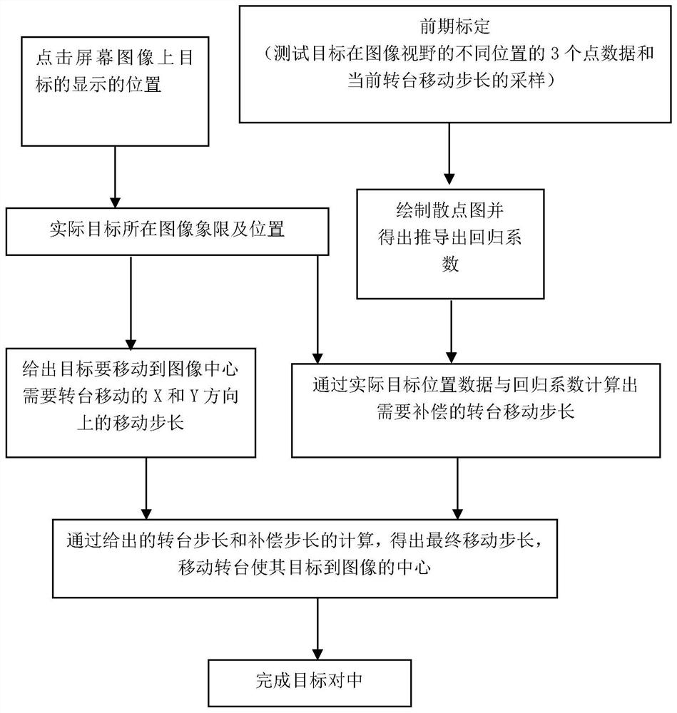
[0041] According to an embodiment of the present application, refer to Figure 1-Figure 3 , the photoelectric tracking image alignment method for the anti-sniper robot of this program, including the following steps:

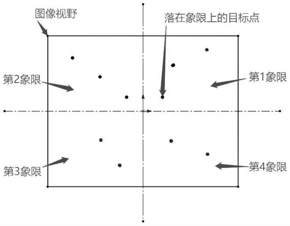
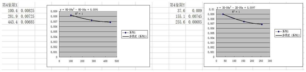
[0042] S1. Collect the coordinate point data of the quadrant where the test target is located multiple times, and perform sampling of the current turntable movement step, specifically including:

[0043] Step...


PUM


Abstract

The invention discloses a photoelectric tracking image alignment method for an anti-sniper robot, and the method comprises the steps: S1, collecting coordinate point data of a quadrant where a test target is located for multiple times, and sampling the current movement step length of a rotary table; s2, drawing a scatter diagram, performing linear regression analysis by adopting the scatter diagram, and deducing to obtain a regression coefficient; s3, clicking a target display position on the screen image to obtain an image quadrant and a position where an actual target is located; s4, giving a turntable moving step length required for moving the target to an image center; s5, according to the actual target position data and the regression coefficient, calculating a rotary table movement step length needing to be compensated; and S6, calculating to obtain a final moving step length, and moving the target to the center of the image by the moving turntable. Linear regression analysis is carried out in a scatter diagram sampling mode, the automatic alignment precision of the equipment is improved based on the obtained regression coefficient, centering aiming can be rapidly carried out on the target after the target is found, and subsequent striking or suppressing operation is rapidly carried out.

Description

technical field [0001] The invention belongs to the technical field of image alignment, and in particular relates to a photoelectric tracking image alignment method for an anti-sniper robot. Background technique [0002] Laser detection technology uses the principle that the optical sight on the enemy sniper rifle is easy to reflect light to detect the position of the enemy sniper. The system using this technology is composed of infrared semiconductor laser illuminator, eye protection laser range finder, video camera and global positioning system. It uses the "cat's eye" effect, that is, when the laser actively irradiates the monitoring area, if there is a visible light and near-infrared optical system in the irradiated area, the optical elements on the focal plane of the optical system will reflect back to the laser in a directional way, and generally the directional reflected laser The energy density is 10,000 times that of other non-optical areas, so it is picked up by t...

Claims


Application Information

Patent Timeline
Patent Type & Authority Applications(China)
IPC IPC(8): F41G1/46F41G1/16G06T7/70
CPCF41G1/46F41G1/16G06T7/70
Inventor 黄强唐剑杨俊永周勇达君
Owner 绵阳久强智能装备有限公司
Why Eureka
Try Eureka