
Asymmetric flowing gas stimulated Raman scattering frequency conversion device

A technology of stimulated Raman scattering and flowing gas. It is applied in the direction of laser scattering effect, laser, electrical components, etc. It can solve the problems of uneven gas density, beam drift, low repetition frequency, etc., and improve the frequency conversion effect and stability. , The effect of reducing uneven airflow and simplifying the overall structure

Pending Publication Date: 2022-03-15
DALIAN INST OF CHEM PHYSICS CHINESE ACAD OF SCI
View PDF0 Cites 0 Cited by
  • Summary
  • Abstract
  • Description
  • Claims
  • Application Information

AI Technical Summary

Problems solved by technology

However, when the heat generated during the stimulated Raman frequency conversion process is large or the laser repetition rate used is high, the heat generated at the laser focus position may not be able to diffuse out in time, resulting in a decrease in Raman frequency conversion efficiency, beam drift or Undesirable consequences such as thermal distortion, the reasons include the uneven gas density in the Raman cell caused by thermal effects (such as thermal lens effect), or the disordered flow of gas molecules caused by temperature differences to generate local eddies, etc.
As a result, the stimulated Raman scattering frequency conversion device can only work at a lower repetition rate, or cannot be applied to Raman frequency conversion of higher power lasers

Method used


Image

  • Asymmetric flowing gas stimulated Raman scattering frequency conversion device

Examples


Embodiment 1

[0028] Example 1: Based on high pressure CO 2 Stimulated Raman scattering frequency conversion device.

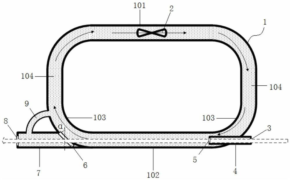
[0029] Such as figure 1 As shown, put CO at a pressure of 10atm 2 The gas is filled into the closed main gas circulation pipeline 1, and the airflow drive device 2 is controlled to drive the high-pressure CO 2 The gas flows clockwise, and the air flow enters the light-transmitting section 102 through the connecting section 104 on one side, is output from the light-passing section 102, and then enters the air-flow driving section 101 from the connecting section 104 on the other side, forming a circular flow. In this embodiment, the gas flow rate is controlled by controlling the speed of the airflow driving device 2 (fan), so as to adapt to different heat dissipation requirements. The flow guide balance tube 9 connects the output light guide arm 7 with the main gas circulation pipeline 1 to ensure output isolation. The air pressure on both sides of the optical window 6 is ...

Embodiment 2

[0034] Embodiment 2, based on high pressure N 2 Stimulated Raman scattering frequency conversion device.

[0035] Such as figure 1 As shown, put the pressure at 10atm of N 2 The gas is filled into the closed main gas circulation pipeline 1, and the air flow driving device 2 is controlled to drive the high pressure N 2 The gas flows clockwise, and the air flow enters the light-transmitting section 102 through the connecting section 104 on one side, is output from the light-passing section 102, and then enters the air-flow driving section 101 from the connecting section 104 on the other side, forming a circular flow. In this embodiment, the gas flow rate is controlled by controlling the speed of the airflow driving device 2 (fan), so as to adapt to different heat dissipation requirements. The flow guide balance tube 9 connects the output light guide arm 7 with the main gas circulation pipeline 1 to ensure output isolation. The air pressure on both sides of the optical window ...

Embodiment 3

[0040] Embodiment three, based on high pressure N 2 Stimulated Raman scattering frequency conversion device.

[0041] Such as figure 1 As shown, put the pressure at 10atm of N 2 The gas is filled into the closed main gas circulation pipeline 1, and the air flow driving device 2 is controlled to drive the high pressure N 2 The gas flows clockwise, and the air flow enters the light-transmitting section 102 through the connecting section 104 on one side, is output from the light-passing section 102, and then enters the air-flow driving section 101 from the connecting section 104 on the other side, forming a circular flow. In this embodiment, the gas flow rate is controlled by controlling the speed of the airflow driving device 2 (fan), so as to adapt to different heat dissipation requirements. The flow guide balance tube 9 connects the output light guide arm 7 with the main gas circulation pipeline 1 to ensure output isolation. The air pressure on both sides of the optical win...


PUM


Abstract

The invention relates to the technical field of Raman laser, in particular to an asymmetric flowing gas stimulated Raman scattering frequency conversion device, which is characterized in that a gas circulation main pipeline is a closed pipeline, one side of the gas circulation main pipeline is a gas flow driving section, the other side of the gas circulation main pipeline is a light transmission section, and the gas flow driving section is provided with a gas flow driving device; one end of the light-passing section is coaxially connected with the input light guide arm, the other end of the light-passing section is coaxially connected with the output light guide arm, a laser input cavity mirror is arranged at the end, located outside the light-passing section, of the input light guide arm, and an input isolation optical window is arranged at the end, located inside the light-passing section, of the input light guide arm. An output isolation optical window inclining outwards is arranged at the end, connected with the light passing section, of the output light guide arm, a laser output cavity mirror is arranged at the end, away from the light passing section, of the output light guide arm, and a flow guide balance pipe is arranged at one end of the gas circulation main pipeline and communicated with the output light guide arm. The Raman medium circularly flows, the light passing section is kept in a good laminar flow state, heat dissipation is guaranteed, the conditions of deflection distortion and the like of a laser light path are reduced, and the device can be used for Raman frequency conversion of high-power or high-repetition-frequency laser.

Description

technical field [0001] The invention relates to the technical field of Raman lasers, in particular to an asymmetric flowing gas stimulated Raman scattering frequency conversion device. Background technique [0002] Stimulated Raman scattering technology is a common laser frequency conversion method. Its advantages are simple device design, convenient debugging, and various stimulated Raman media that can be selected. Different Raman media have different spectral shift ranges for pump lasers. For example, a solid can produce a movement of tens of hundreds of wavenumbers, while a gas Raman medium can produce a frequency shift of thousands of wavenumbers. Therefore, the transformation span using Raman frequency conversion is relatively large, and the variable wavelengths are abundant. Currently commonly used Raman media are crystals (such as: diamond, SrWO 4 ), liquid (such as: H 2 O, CS 2 , C 6 h 6 ) and gases (such as: H 2 , CH 4 ), in which the stimulated Raman freque...

Claims


Application Information

Patent Timeline
IPC IPC(8): H01S3/034H01S3/036H01S3/10H01S3/102H01S3/104H01S3/30
CPCH01S3/305H01S3/104H01S3/1026H01S3/10H01S3/036H01S3/034
Inventor 刘金波蔡向龙郭敬为李仲慧
Owner DALIAN INST OF CHEM PHYSICS CHINESE ACAD OF SCI
Learn More