Multifunctional operation rack for hand and foot surgery department

An operating table and multi-functional technology, applied in the direction of operating table, surgery, medical science, etc., can solve the problems of inconvenient operation and treatment for medical staff, cumbersome operation of a single leg, troublesome limit operation, etc., to achieve convenient treatment and rehabilitation High performance, wide range of applications, avoiding the effect of shaking from side to side

Inactive Publication Date: 2022-03-18
陈光鑫
View PDF0 Cites 0 Cited by
  • Summary
  • Abstract
  • Description
  • Claims
  • Application Information

AI Technical Summary

Problems solved by technology

[0003] In order to facilitate the treatment of the patient's hands and feet, there are often some places on the surface of the hand and foot surgery table for medical staff to place the hands and feet, in order to avoid foot or foot pain during the treatment process. However, some existing operating platforms also have some problems when limiting and fixing the feet:
[0004] First: Due to the different foot sizes of different patients, some existing limit fixing devices can only fix specific foot sizes, and the limit operation for different foot sizes is often troublesome, which affects the treatment of patients;
[0005] Second: Since the patient may treat one leg or both legs during the treatment process, some existing equipment only lifts both legs unilaterally, and the operation of lifting a single leg is more cumbersome;
[0006] Third: In the process of treating the patient's legs, if the abdomen of the legs also needs to be treated, the existing equipment is more troublesome when turning the legs, which is inconvenient for medical staff to operate and treat

Method used


Image

  • Multifunctional operation rack for hand and foot surgery department
  • Multifunctional operation rack for hand and foot surgery department
  • Multifunctional operation rack for hand and foot surgery department

Examples


Embodiment

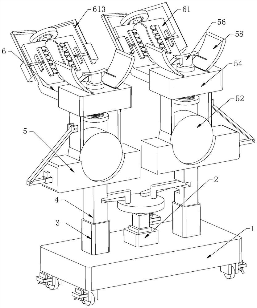
[0037] Example: such as figure 1 As shown, a multifunctional operating table for hand and foot surgery includes a mobile base 1, a cylinder base 2, a mounting base 3, a support rod 4, an adjustment mechanism 5 and a snap-in mechanism 6, and the middle part of the upper surface of the mobile base 1 is fixedly installed with The cylinder seat 2 and the upper surface of the mobile seat 1 are symmetrically connected with mounting seats 3 on the left and right sides, and the insides of the two mounting seats 3 are connected with support rods 4 through sliding fit, and the upper end of a single support rod 4 is connected with an adjustment mechanism 5 , The rear side of the adjustment mechanism 5 is provided with an engaging mechanism 6 near the upper end.

[0038] In this embodiment, the mobile seat 1 is an existing universal wheel with a limit function, and the device can be moved to a suitable place and fixed on the ground to improve the stability of the movement and support of t...


PUM


Abstract

The invention discloses a multifunctional operation rack for the hand and foot surgery department, and particularly relates to the field of operation racks, the multifunctional operation rack comprises a moving seat, an air cylinder seat, mounting seats, a supporting rod, an adjusting mechanism and a clamping mechanism, the air cylinder seat is fixedly mounted in the middle of the upper surface of the moving seat, and the mounting seats are symmetrically connected to the left side and the right side of the upper surface of the moving seat; the two mounting bases are located on the side away from the air cylinder base, supporting rods are connected to the interiors of the two mounting bases in a sliding fit mode, an adjusting mechanism is connected to the upper end of each supporting rod, a clamping mechanism is arranged on the portion, close to the upper end, of the rear side of each adjusting mechanism, and a clamping base is fixedly connected to the upper surface of the air cylinder base; and the upper surface of the clamping seat is rotationally connected with a first rotating disc through a rotating shaft. According to the leg lifting device, a single leg or two legs can be lifted according to the legs, needing to be treated, of a patient, the legs can be deflected to expose the leg abdomen, and medical staff can conveniently treat the leg abdomen.

Description

technical field [0001] The invention relates to the technical field of operating benches, in particular to a multifunctional operating bench for hand and foot surgery. Background technique [0002] Hand and foot surgery mainly treats the hands and feet of patients. During the treatment process, some protective measures and tools are usually used to help the treatment and care, and play a certain role in promoting the recovery of patients. The hand and foot surgery operating table is A commonly used medical device. [0003] In order to facilitate the treatment of the patient's hands and feet, there are often some places on the surface of the hand and foot surgery table for medical staff to place the hands and feet, in order to avoid foot or foot pain during the treatment process. However, some existing operating platforms also have some problems when limiting and fixing the feet: [0004] First: Due to the different foot sizes of different patients, some existing limit fixi...

Claims


Application Information

Patent Timeline
Patent Type & Authority Applications(China)
IPC IPC(8): A61G13/12
CPCA61G13/1245A61G13/125A61G13/128
Inventor 陈光鑫
Owner 陈光鑫
Why Eureka
Try Eureka