Roller cleaning device with crack repairing structure
A technology for repairing structures and cleaning devices, which is applied in the field of roll cleaning and can solve problems such as lack of drying structures
- Summary
- Abstract
- Description
- Claims
- Application Information
AI Technical Summary
Problems solved by technology
Method used
Image
Examples
Embodiment 2
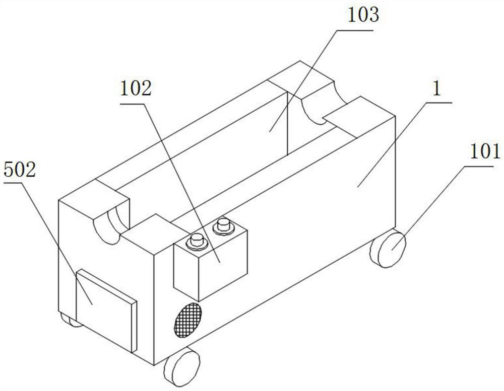
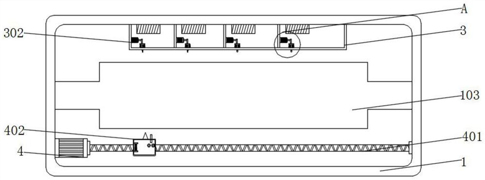
[0043] Example 2: see image 3 , Figure 7 and Figure 8 , an embodiment provided by the present invention: a roll cleaning device with a crack repair structure, an ultrasonic flaw detector 301 is installed on the inner wall of the detector 3, a plurality of motors 302 are installed on the inner wall of the detector 3, and the output ends of the motors 302 The impact bar 303 is installed, the first spring 304 is installed on the inner bottom wall of the detector 3, the impact plate 305 is installed on the top of the first spring 304, the marking pen 306 is installed on the bottom of the impact plate 305, the output end of the second motor 4 The first lead screw 401 is installed, the outer wall of the first lead screw 401 is covered with a moving block, the outer wall of the moving block is equipped with a welder 402, the inner wall of the welder 402 is equipped with a drive motor 403, and the output end of the drive motor 403 is installed with Drive wheel, driven wheel 404 i...
Embodiment 3
[0044] Example 3: See Figure 4 and Figure 9 , an embodiment provided by the present invention: a roll cleaning device with a crack repair structure, the inner bottom wall of the main body 1 is equipped with a plurality of fixed shafts, 501, the outer wall of the fixed shaft 501 is equipped with a plurality of rollers, the top of the rollers A collection tank 502 is installed, the inner wall of the collection tank 502 is equipped with a bearing plate 503, the bottom of the load bearing plate 503 is equipped with a lifting rod 504, the outer wall of the lifting rod 504 is equipped with a conductive rod 505, and the inner bottom wall of the collecting tank 502 is installed with a detection resistor 506, the debris after cleaning falls into the collection tank 501 through the inclined plate 5, and then the debris squeezes the load-bearing plate 503, and the load-bearing plate 503 moves downward to drive the lifting rod 504 to move downward, and the lifting rod 504 moves downward...
Embodiment 4
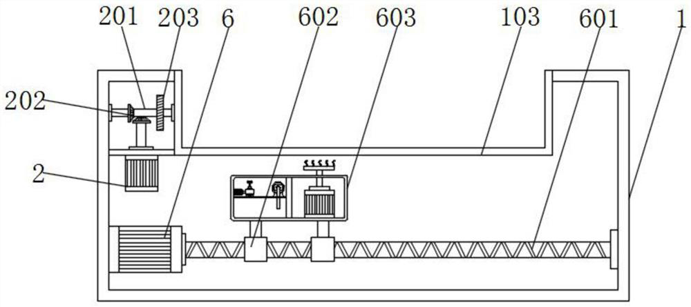
[0045] Example 4: See figure 2 , Figure 5 and Figure 6 , an embodiment provided by the present invention: a roll cleaning device with crack repair structure, the output end of the first motor 6 is equipped with a second lead screw 601, the outer wall of the second lead screw 601 is covered with a sliding block 602, sliding The outer wall of the block 602 is equipped with a cleaner 603, the inner bottom wall of the cleaner 603 is equipped with a storage tank 604, the top of the storage tank 604 is equipped with a water pump 605, the input end of the water pump 605 is equipped with a water inlet pipe, and one end of the water inlet pipe extends into In the inside of the storage case 604, a fourth motor 606 is installed on the inwall of the cleaner 603, a cam 607 is installed on the output end of the fourth motor 606, a pulley 611 is installed on the top of the storage case 604, and a moving frame 608 is installed on the top of the pulley 611. Back-moving springs 610 are ins...
PUM
 Abstract
Description
Claims
Application Information
 - R&D
- Intellectual Property
- Life Sciences
- Materials
- Tech Scout
- Unparalleled Data Quality
- Higher Quality Content
- 60% Fewer Hallucinations
Browse by: Latest US Patents, China's latest patents, Technical Efficacy Thesaurus, Application Domain, Technology Topic, Popular Technical Reports.
© 2025 PatSnap. All rights reserved.Legal|Privacy policy|Modern Slavery Act Transparency Statement|Sitemap|About US| Contact US: help@patsnap.com


