Eureka AIR delivers breakthrough ideas for toughest innovation challenges, trusted by R&D personnel around the world.

Mechanical arm for numerical control machine tool

A technology of CNC machine tools and robotic arms, applied in metal processing machinery parts, metal processing equipment, maintenance and safety accessories, etc. Effect

Active Publication Date: 2022-03-18
东莞市宝科精密机械有限公司
View PDF5 Cites 0 Cited by
  • Summary
  • Abstract
  • Description
  • Claims
  • Application Information

AI Technical Summary

Problems solved by technology

[0004] The purpose of the present invention is to solve the problem in the prior art that the middle part of the X-axis screw rod of the CNC machine tool is easy to bear large torsional force and shear force, and proposes a mechanical arm for the CNC machine tool.

Method used


Image

  • Mechanical arm for numerical control machine tool
  • Mechanical arm for numerical control machine tool
  • Mechanical arm for numerical control machine tool

Examples


Embodiment 1

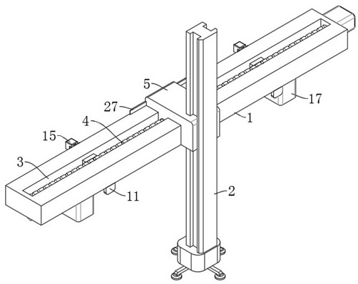
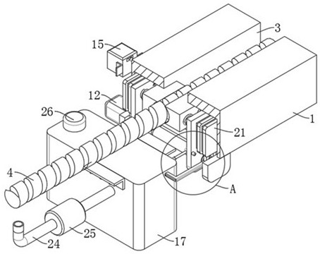
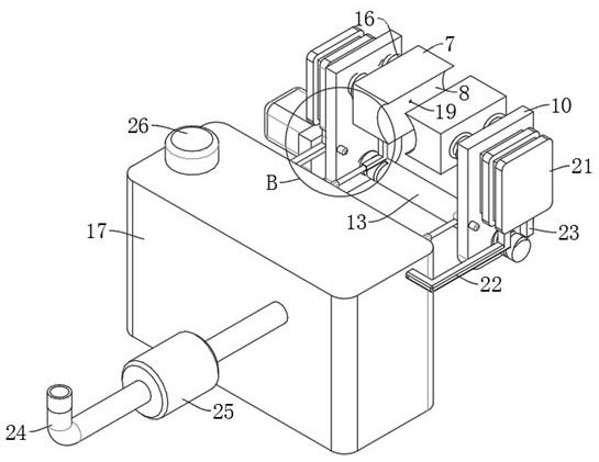
[0030] refer to Figure 1-6 , a mechanical arm for a numerically controlled machine tool, comprising a Y-axis slide rail 1 provided with a chute 3 and a screw mandrel 4, and also comprising: a sliding seat 5 threaded on the screw mandrel 4 and slidably connected in the chute 3, Wherein, the sliding seat 5 is slidably connected with a Z-axis swing arm 2 with a handle at the lower end; the clamping part is arranged on the left and right inner walls of the chute 3 and is located in the middle of the Y-axis slide rail 1, wherein the clamping part includes Sliding holes 6 are provided on the left and right inner walls of the chute 3, and sliders 7 are slidably connected in the two sliding holes 6, and the opposite side walls of the two sliders 7 are provided with arc-shaped grooves 8 that are offset against the outer wall of the screw rod 4 , the lower end of the Y-axis slide rail 1 is provided with an opening and closing mechanism connected with the two sliders 7; the oil storage ...

Embodiment 2

[0034] refer to Figure 2-6 , which is basically the same as that of Embodiment 1, furthermore: the opening and closing mechanism includes two supports 11 fixedly installed at the lower end of the Y-axis slide rail 1, and a double-ended threaded rod 13 is installed in rotation between the two supports 11, wherein A drive motor 12 is fixedly installed on the outer wall of a support 11, the output end of the drive motor 12 is fixedly connected with one end of a double-ended threaded rod 13, and both ends of the double-ended threaded rod 13 are threadedly connected with a slide plate 10 and a Y-axis slide rail Both sides of the lower end of 1 are provided with sliding chambers 9 connected to the sliding holes 6. Two sliding plates 10 are respectively slidably connected in the two sliding chambers 9 and connected with the two sliding blocks 7 respectively. The Y-axis slide rail 1 is provided with The automatic trigger mechanism connected with the drive motor 12, when the sliding s...

Embodiment 3

[0037] refer to figure 1 , figure 2 as well as Figure 5 , which is basically the same as in Embodiment 1, furthermore: the automatic trigger mechanism includes a reverse button 15 fixedly installed on the Y-axis slide rail 1, the reverse button 15 is aligned with the position of the slider 7, and the reverse button 15 is aligned with the position of the slider 7 The driving motor 12 is electrically connected, and both sides of the sliding seat 5 are fixedly connected with a trigger lever 27 cooperating with the reverse button 15, and both sides of the slide plate 10 are fixedly installed with a limit switch 14 electrically connected with the driving motor 12, When the sliding seat 5 is moving, when the reverse button 15 is touched by the trigger lever 27, the driving motor 12 will drive the double-ended threaded rod 13 to rotate in the opposite direction. When the sliding seat 5 passes over the slider 7, the sliding seat 5 will simultaneously Separated from the reverse butto...


PUM


Abstract

The invention discloses a mechanical arm for a numerical control machine tool and belongs to the field of numerical control machine tools. A mechanical arm for a numerical control machine tool comprises a Y-axis sliding rail provided with a sliding groove and a lead screw, and further comprises a sliding seat in threaded connection with the lead screw and in sliding connection with the interior of the sliding groove, and a Z-axis swing arm with a gripper at the lower end is in sliding connection with the sliding seat; the clamping pieces are arranged on the left inner wall and the right inner wall of the sliding groove and located in the middle of the Y-axis sliding rail, each clamping piece comprises sliding holes formed in the left inner wall and the right inner wall of the sliding groove, sliding blocks are connected into the two sliding holes in a sliding mode, and cambered surface grooves abutting against the outer wall of the lead screw are formed in the opposite side walls of the two sliding blocks. An opening and closing mechanism connected with the two sliding blocks is arranged at the lower end of the Y-axis sliding rail. The oil storage tank is fixedly mounted at the lower end of the Y-axis sliding rail; torsional force and shear force borne by the lead screw during rotation can be effectively shared through the two sliding blocks, and therefore the service life of the lead screw is prolonged.

Description

technical field [0001] The invention relates to the technical field of numerical control machine tools, in particular to a mechanical arm for numerical control machine tools. Background technique [0002] CNC machine tool is the abbreviation of numerical control machine tool, which is an automatic machine tool equipped with a program control system. The control system can logically process programs with control codes or other symbolic instructions, decode them, express them in coded numbers, and input them into the numerical control device through the information carrier. After calculation and processing, various control signals are sent by the numerical control device to control the movement of the machine tool, and the parts are automatically processed according to the shape and size required by the drawing. [0003] Existing CNC machine tools can automatically pick up blanks and place processed parts through the mechanical arm when processing parts. When using a mechanic...

Claims


Application Information

Patent Timeline
Patent Type & Authority Applications(China)
IPC IPC(8): B23Q7/04B23Q11/12
CPCB23Q7/04B23Q11/10B23Q11/125
Inventor 邢威余丕亮华文灶
Owner 东莞市宝科精密机械有限公司
Why Eureka
Eureka Blog
Learn More