Device capable of automatically screwing for building installation

An installation and screwing technology, which is applied in the field of doors and windows, can solve problems such as time-consuming and laborious, screw deviation, and lower product quality, and achieve the effects of convenient operation, increased linkage, and improved work efficiency

Inactive Publication Date: 2022-03-18
徐州多元机械科技有限公司
View PDF0 Cites 0 Cited by
  • Summary
  • Abstract
  • Description
  • Claims
  • Application Information

AI Technical Summary

Problems solved by technology

[0003] During the construction of traditional doors and windows, it is usually necessary to screw the locks of the doors and windows to fix the components of the doors and windows. However, the existing automatic screwing device has a low degree of automation and usually requires manual hand-held operation, but manually uses an electric screwdriver to screw the screws There is a certain uncontrollable risk. Because the electric screwdriver is easy to tilt when screwing manually, it is easy to cause the screw to deviate and reduce the quality of the product. At the same time, when screwing, it is necessary to manually hold the screw for operation, which cannot achieve automatic The purpose of sending nails makes the whole work process more time-consuming and laborious
[0004] Aiming at the deficiencies of the prior art, the present invention provides an automatic screwing device for building installation, which has the advantages of vertical driving and automatic screw feeding, and solves the problem of low automation of the existing automatic screwing device , to ensure that when the device is used for screwing, the screw can be automatically fed, and the screw is driven in vertically to avoid the deviation of the nailing position. Smartness in use

Method used


Image

  • Device capable of automatically screwing for building installation
  • Device capable of automatically screwing for building installation
  • Device capable of automatically screwing for building installation

Examples


Embodiment 1

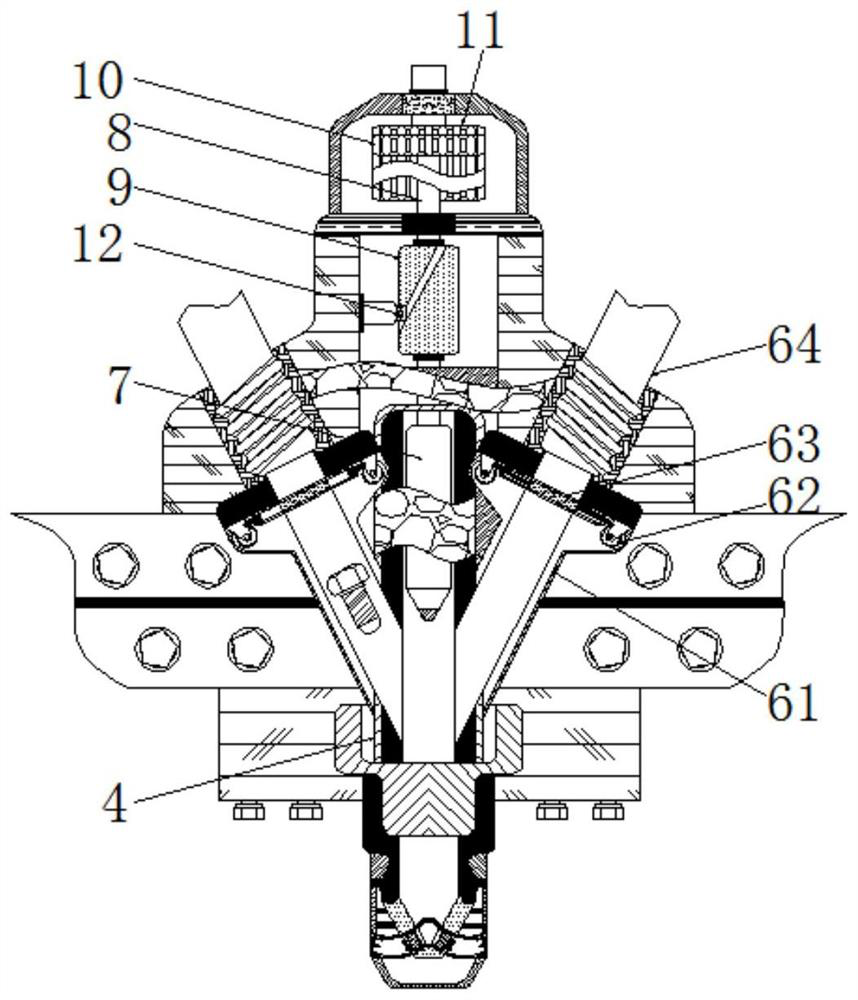
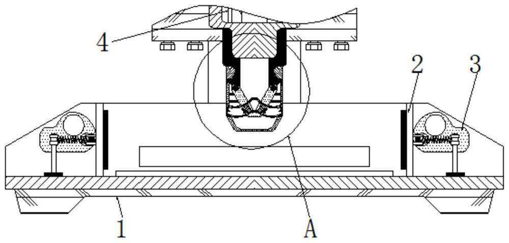
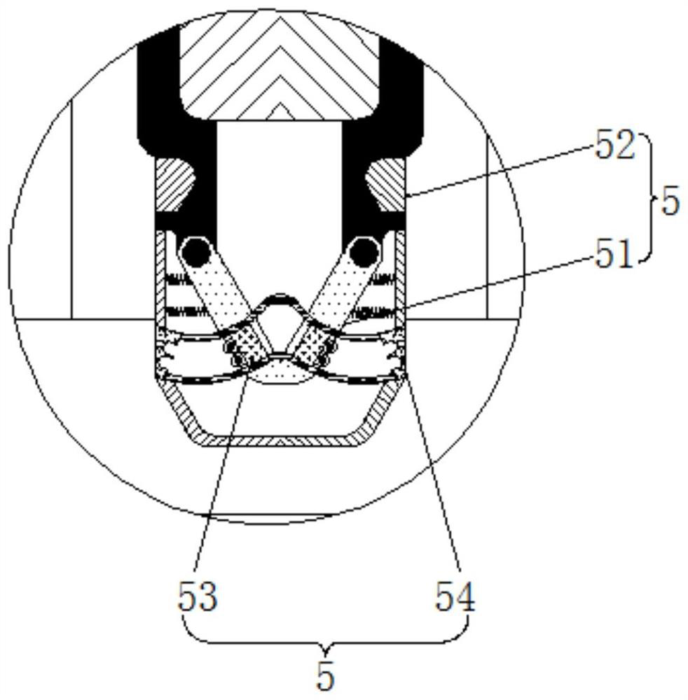
[0028] see figure 1 , a device for automatic screwing for building installation, including a base 1, a conveyor belt is arranged above the base 1, and the conveyor belt is used to drive the doors and windows to automatically transfer, the upper part of the base 1 is clamped with a limiting plate 2, and the limiting plate 2 The side end is rotatably connected with a cam 3, the upper part of the base 1 is fixedly connected with a screw sleeve 4, and the inside of the screw sleeve 4 is provided with a cavity, the size of the cavity is compatible with the size of the screwdriver head 7, and the outer surface of the screw sleeve 4 The mouthpiece mechanism 5 is sleeved on the surface, and the mouthpiece mechanism 5 includes a partition 51. There are two partitions 51. The specifications of the two partitions 51 are consistent, and the size of the spacer sleeve 52 is adapted to each other. At the same time, the partition A spring is arranged between the plate 51 and the limit sleeve ...

Embodiment 2

[0031] see figure 1 , a device for automatic screwing for building installation, including a base 1, a conveyor belt is arranged above the base 1, and the conveyor belt is used to drive the doors and windows to automatically transfer, the upper part of the base 1 is clamped with a limiting plate 2, and the limiting plate 2 The side end is rotatably connected with a cam 3, the upper part of the base 1 is fixedly connected with a screw sleeve 4, and the inside of the screw sleeve 4 is provided with a cavity, the size of the cavity is compatible with the size of the screwdriver head 7, and the outer surface of the screw sleeve 4 The surface is sleeved with a batch nozzle mechanism 5, and the two ends of the screw sleeve 4 are movably connected with a nail feeding mechanism 6. The nail feeding mechanism 6 includes a nail feeding tube 61, and there are two nail feeding tubes 61. The specifications of the two nail feeding tubes 61 Consistent, and symmetrically distributed with refer...

Embodiment 3

[0034] see Figure 1-4, a device for automatic screwing for building installation, including a base 1, a conveyor belt is arranged above the base 1, and the conveyor belt is used to drive the doors and windows to automatically transfer, the upper part of the base 1 is clamped with a limiting plate 2, and the limiting plate 2 The side end is rotatably connected with a cam 3, the upper part of the base 1 is fixedly connected with a screw sleeve 4, and the inside of the screw sleeve 4 is provided with a cavity, the size of the cavity is compatible with the size of the screwdriver head 7, and the outer surface of the screw sleeve 4 The mouthpiece mechanism 5 is sleeved on the surface, and the mouthpiece mechanism 5 includes a partition 51. There are two partitions 51. The specifications of the two partitions 51 are consistent, and the size of the spacer sleeve 52 is adapted to each other. At the same time, the partition A spring is arranged between the plate 51 and the limit sleev...


PUM


Abstract

The invention relates to the technical field of doors and windows, and discloses an automatic screw driving device for building installation, which comprises a base, screw feeding pipes, a turntable, a baffle plate and a screw storage pipe are matched for use, and the baffle plate is driven to synchronously move by the rotation of the turntable, so that the intermittent opening and closing of the two screw feeding pipes are controlled, and the purpose of automatically feeding screws is achieved. Through cooperative use of the partition plates, the limiting sleeves, the inserting plates and the sockets, the two partition plates are pushed to be automatically opened through the gravity of the screws, the inserting plates and the sockets are connected in an inserted mode, a power source is connected, the screwdriver bits are linked to tighten the screws, the linkage performance during screw driving is improved, meanwhile, the limiting sleeves are used for limiting, and the screw driving efficiency is improved. According to the screw tightening device, the rotating shaft, the sleeve rod, the small gear, the large gear, the screwdriver bit and the positioning rib are used in cooperation, the large gear rotates to drive the screwdriver bit to tighten the screw, the screwing height of each time is consistent, and equal-force tightening is guaranteed.

Description

technical field [0001] The invention relates to the technical field of doors and windows, in particular to an automatic screwing device for building installation. Background technique [0002] Windows are an indispensable component in buildings and are often used for lighting, ventilation or decoration of buildings. The standard of windows affects the appearance of buildings and the indoor environment. The doors and windows in the existing construction projects are of various types and styles, which can not only make the appearance of the building more pleasing to the eye, but also improve the ventilation and ventilation effects of the building to varying degrees. [0003] During the construction of traditional doors and windows, it is usually necessary to screw the locks of the doors and windows to fix the components of the doors and windows. However, the existing automatic screwing device has a low degree of automation and usually requires manual hand-held operation, but m...

Claims


Application Information

Patent Timeline
Patent Type & Authority Applications(China)
IPC IPC(8): B25B21/00B25B23/04
CPCB25B21/00B25B23/04
Inventor 姚辉福
Owner 徐州多元机械科技有限公司
Why Eureka
Try Eureka