Injection molding mold and injection molding method using same

A technology of injection molding and moulds, which is applied in the field of injection molding moulds, can solve the problems of high labor intensity, labor cost and time cost, and low work efficiency of operators, so as to reduce production labor intensity, improve production efficiency, and improve yield rate and appearance quality

Pending Publication Date: 2022-03-18
SHANGHAI CHUANGGONG COMM TECH
View PDF11 Cites 0 Cited by
  • Summary
  • Abstract
  • Description
  • Claims
  • Application Information

AI Technical Summary

Problems solved by technology

[0004] However, the method of cutting the gate (waste) with a jig after injection molding consumes labor costs and time costs, and the labor intensity of the operators is high and the work efficiency is low.

Method used


Image

  • Injection molding mold and injection molding method using same
  • Injection molding mold and injection molding method using same
  • Injection molding mold and injection molding method using same

Examples


Embodiment 1

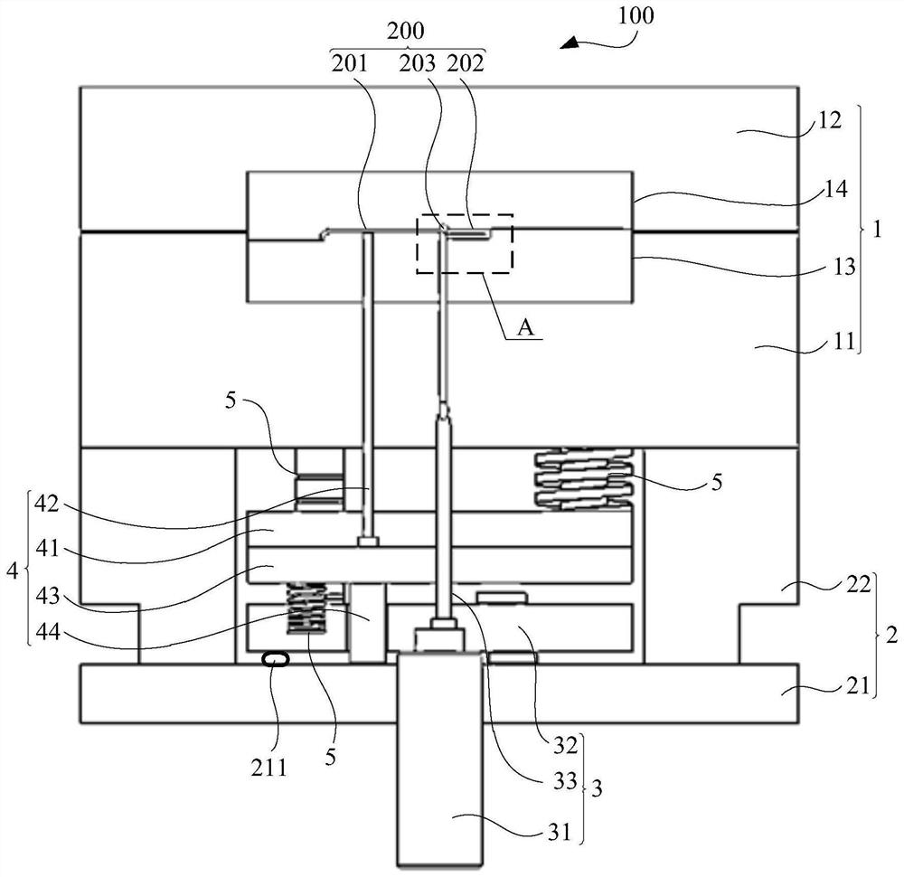
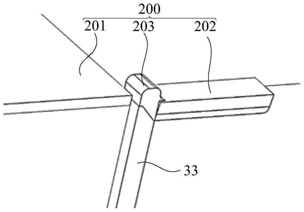
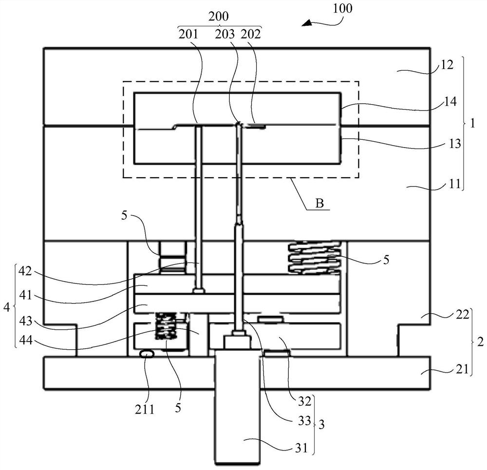
[0045] figure 1 Schematic diagram of the structure of the injection molding mold provided by Embodiment 1 of the present invention; figure 2 for figure 1 The three-dimensional schematic diagram of A; image 3 for figure 1 A schematic diagram of the state of the injection molding mold in ; Figure 4 for image 3 Partial enlarged view of B in middle; Figure 5 for figure 1 Another state diagram of the injection molding mold in ; Image 6 for Figure 5 The three-dimensional schematic diagram at C.

[0046] refer to figure 1 and figure 2As shown, the injection molding mold 100 provided in this embodiment includes a mold base component 1 , a support component 2 , a first jacking component 3 and a second jacking component 4 . Wherein, the mold base assembly 1 is used to form the injection molded part 200, and the support assembly 2 is used to support the mold base assembly 1, for example, the bottom end of the support assembly 2 is supported on the ground or on a mounti...

Embodiment 2

[0082] Figure 7 It is a schematic flow chart of the injection molding method provided by the second embodiment of the invention. refer to Figure 7 As shown, this embodiment provides an injection molding method, which is applied to the injection molding mold 100 of Embodiment 1 for injection molding plastic parts.

[0083] Specifically, the method includes the following steps:

[0084] S100. Inject molten plastic into the mold base assembly to form a molten injection molded part; wherein, the injection molded part includes an injection molded body and a gate connected to the injection molded body, and the connection between the gate and the injection molded body is cut off department.

[0085] combine figure 1 As shown, first, the molten plastic is injected into the mold base assembly 1 through the injection machine, specifically, the molten plastic is injected into the injection cavity formed between the fixed plate 13 and the movable plate 14 in the mold base assembly 1...


PUM


Abstract

The invention provides an injection molding mold and an injection molding method using the same. The invention provides an injection molding mold. The injection molding mold comprises a mold frame assembly, a supporting assembly, a first jacking assembly and a second jacking assembly. The mold frame assembly is supported at the top end of the supporting assembly and is used for molding an injection molding part; the second jacking assembly is located between the first jacking assembly and the mold frame assembly, the first jacking assembly comprises a cutter, and the second jacking assembly comprises at least one ejector pin; when the first jacking assembly moves towards the mold frame assembly to a first position, the cutter penetrates through a cutting part of the injection molding part to separate a sprue part of the injection molding part from an injection molding body, and the ejector pin is located at an initial position; and when the first jacking assembly jacks up the second jacking assembly and moves towards the mold frame assembly to a second position, the ejector rod jacks up the injection molding body. The injection molding mold is high in operation efficiency, and the product yield can be increased.

Description

technical field [0001] The invention relates to the technical field of injection molding, in particular to an injection molding mold and an injection molding method using the same. Background technique [0002] Injection molding machine, also known as injection molding machine or injection machine, is the main molding equipment for making thermoplastics or thermosetting plastics into various shapes of plastic products using plastic molding molds. Injection molding machines can be divided into vertical type, horizontal type and vertical-horizontal compound type according to the arrangement of injection device and clamping device. [0003] The injection molding machine is usually composed of an injection molding system, a mold clamping system, a transmission system electrical control system, a heating and cooling system, etc. The injection mold is controlled by the injection molding machine to close the mold, and under a certain pressure and speed, the molten metal is melted t...

Claims


Application Information

Patent Timeline
Patent Type & Authority Applications(China)
IPC IPC(8): B29C45/38B29C45/40
CPCB29C45/38B29C45/4005
Inventor 许汪
Owner SHANGHAI CHUANGGONG COMM TECH
Why Eureka
Try Eureka