Vacuum pump decompression device

A technology of decompression device and vacuum pump, applied in pump control, pump components, variable capacity pump components, etc., can solve the problems of pressure rise at the end of the vacuum pump, damage to the vacuum pump, pressure rise, etc., to achieve flexible switching and improve intelligence performance, the effect of ensuring independence

Pending Publication Date: 2022-03-18
山东凯恩真空技术有限公司
View PDF4 Cites 0 Cited by
  • Summary
  • Abstract
  • Description
  • Claims
  • Application Information

AI Technical Summary

Problems solved by technology

[0003] At present, most of the vacuum pumps on the market will increase the air pressure of the exhaust part when they are operated for a long time. The exhaust quality of the body, the motor will increase the force to exhaust the vacuum pump, which will lead to a further increase in the air pressure at the end of the vacuum pump. It is particularly important to decompress the vacuum pump

Method used


Image

  • Vacuum pump decompression device
  • Vacuum pump decompression device
  • Vacuum pump decompression device

Examples


Embodiment Construction

[0033] The technical solutions in the embodiments of the present invention will be clearly and completely described below with reference to the accompanying drawings in the embodiments of the present invention. Obviously, the described embodiments are only a part of the embodiments of the present invention, but not all of the embodiments. Based on the embodiments of the present invention, all other embodiments obtained by those of ordinary skill in the art without creative efforts shall fall within the protection scope of the present invention.

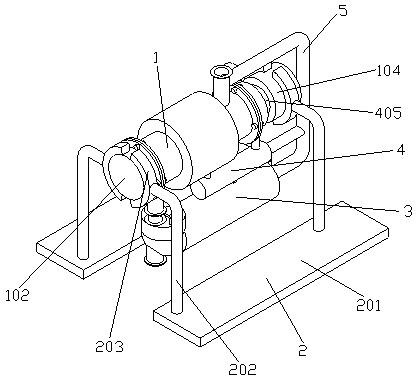
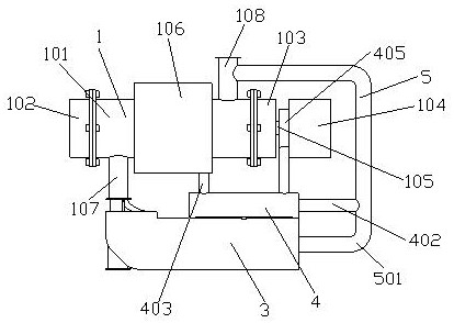
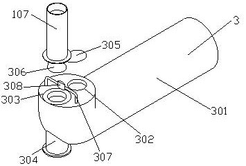
[0034] see Figure 1-10 , the present invention provides a technical solution: a vacuum pump decompression device, comprising a vacuum pump body 1, the vacuum pump body 1 includes a main pump cavity 101, the front end of the main pump cavity 101 is fixedly connected with a front cavity 102 by screws, and the main body pump cavity 101 The rear end is fixedly connected to the rear cavity 103 by screws, the rear end of the main pump cavi...


PUM


Abstract

The invention discloses a vacuum pump decompression device, and relates to the technical field of vacuum pumps. The vacuum pump pressure reducing device comprises a vacuum pump body, the vacuum pump body comprises a main body pump cavity, the front end of the main body pump cavity is fixedly connected with a front cavity through screws, the rear end of the main body pump cavity is fixedly connected with a rear cavity through screws, a motor is arranged at the rear end of the main body pump cavity, and an output shaft is fixedly installed at the front end of the motor; the front end of the output shaft penetrates through the rear cavity to be connected with a screw in the main body pump cavity, the outer side of the middle of the main body pump cavity is covered with a cooling outer cylinder, the lower side of the front end of the main body pump cavity is fixedly connected with an outlet pipe in a penetrating mode, and the upper side of the rear end of the main body pump cavity is fixedly connected with an inlet pipe in a penetrating mode. The first pressure reducing device comprises a first pressure reducing pipe, the first pressure reducing pipe is in an L shape, a pressure reducing circular groove is formed in the rear side of the upper surface of the first pressure reducing pipe, and the pressure reducing speed of the vacuum pump pressure reducing device is higher.

Description

technical field [0001] The invention relates to the technical field of vacuum pumps, in particular to a vacuum pump decompression device. Background technique [0002] A vacuum pump refers to a device or device that uses mechanical, physical, chemical or physicochemical methods to evacuate the evacuated container to obtain a vacuum. Generally speaking, a vacuum pump is a device that uses various methods to improve, generate and maintain vacuum in a certain closed space. According to the working principle of vacuum pumps, vacuum pumps can basically be divided into two types, namely gas capture pumps and gas transfer pumps. It is widely used in metallurgy, chemical industry, food, electronic coating and other industries. [0003] At present, most of the vacuum pumps on the market will increase the air pressure of the exhaust part when they are operated for a long time. The exhaust quality of the body, the motor will increase the force to exhaust the vacuum pump, which will ...

Claims


Application Information

Patent Timeline
Patent Type & Authority Applications(China)
IPC IPC(8): F04B39/00F04B39/12F04B49/08
CPCF04B39/00F04B39/123F04B49/08
Inventor 赵彬彬
Owner 山东凯恩真空技术有限公司
Why Eureka
Try Eureka