
Resistor heat resistance detection device for high-temperature area of electronic equipment

A technology for electronic equipment and heat resistance, which is applied in the field of resistance heat resistance detection devices, can solve the problems of large influence on the service life of the resistance, poor uniformity of heating on the surface of the resistance to be measured, and low accuracy of detection data, so as to avoid detection data. Inaccurate, enriching the performance of comprehensive indicators, reducing the effect of contact area

Pending Publication Date: 2022-03-18
深圳市东凌电子有限公司
View PDF0 Cites 0 Cited by
  • Summary
  • Abstract
  • Description
  • Claims
  • Application Information

AI Technical Summary

Problems solved by technology

[0003] Existing resistance heat resistance detection devices used in high-temperature areas of electronic equipment usually place the resistance to be tested in a detection box when testing, and pass high-temperature gas into the detection box to make the resistance in a high-temperature environment , and put the resistor in the detection circuit by introducing the circuit, and judge the heat resistance performance of the resistor by detecting the indicators of the resistor in the high temperature environment. However, when the electronic equipment used in the high temperature area is actually used, there is a high temperature environment. Immediately shut down the fast cooling zone, and restart after cooling for a certain period of time, there is an alternating situation of high and low ambient temperature, and the alternating switching of high and low temperature environments has a great impact on the service life of the resistor. Carrying out continuous performance testing, it is impossible to effectively complete the heat resistance performance testing in a small alternating environment, and the actual testing effect is not good
[0004] In addition, the existing resistance heat resistance detection device used in the high temperature area of ​​electronic equipment usually puts the resistance to be tested in the detection box during use, and is electrically connected to the circuit. When measuring the resistance, the surface of the resistance to be measured is blocked by the access circuit equipment. When the hot air is actually introduced, the hot air in the test box cannot achieve a uniform temperature rise of the resistance to be measured during the flow process, because the surface of the actual resistance installation position is blocked. The area of ​​the resistance is different, and the absolute performance of the resistance under the condition of unaffected conditions should be detected during the test. However, in the initial heating stage of the current detection, the heating uniformity of the surface of the resistance to be tested is poor, and the detection data accuracy in the initial temperature rise situation is low. The actual detection effect is not good

Method used


Image

  • Resistor heat resistance detection device for high-temperature area of electronic equipment
  • Resistor heat resistance detection device for high-temperature area of electronic equipment
  • Resistor heat resistance detection device for high-temperature area of electronic equipment

Examples


no. 1 example

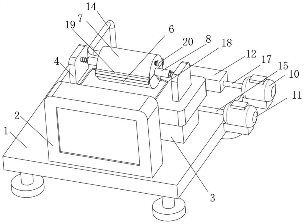
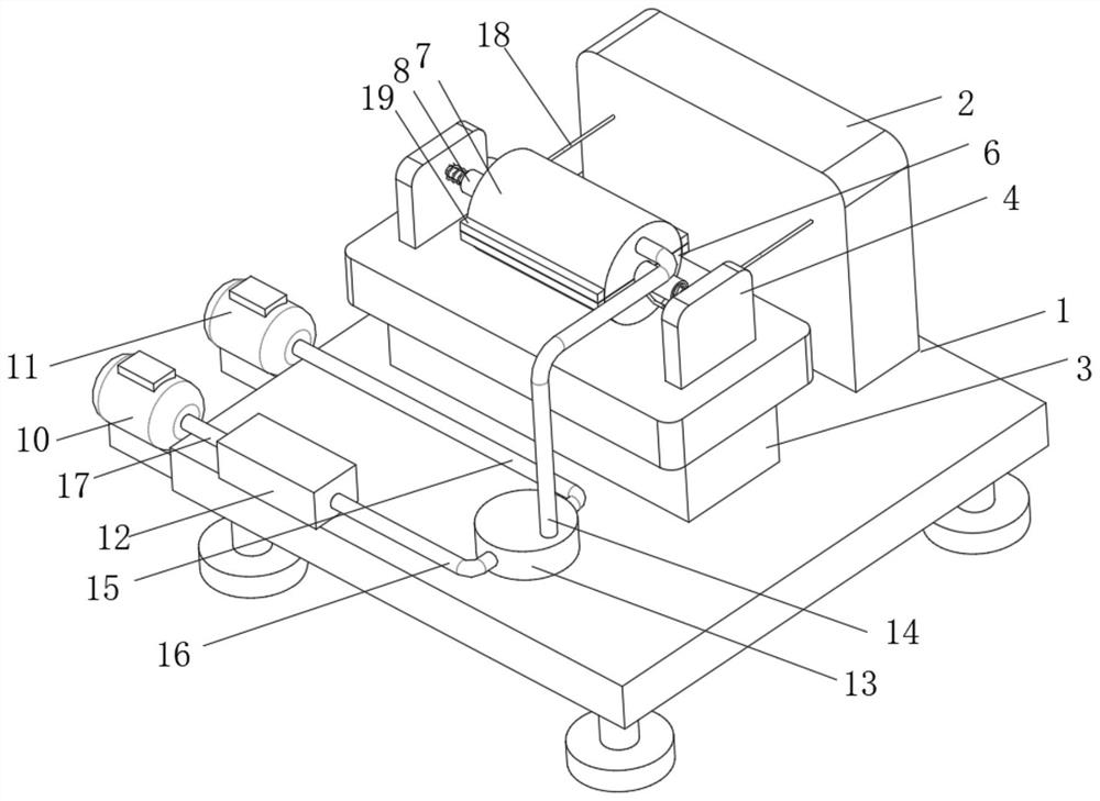
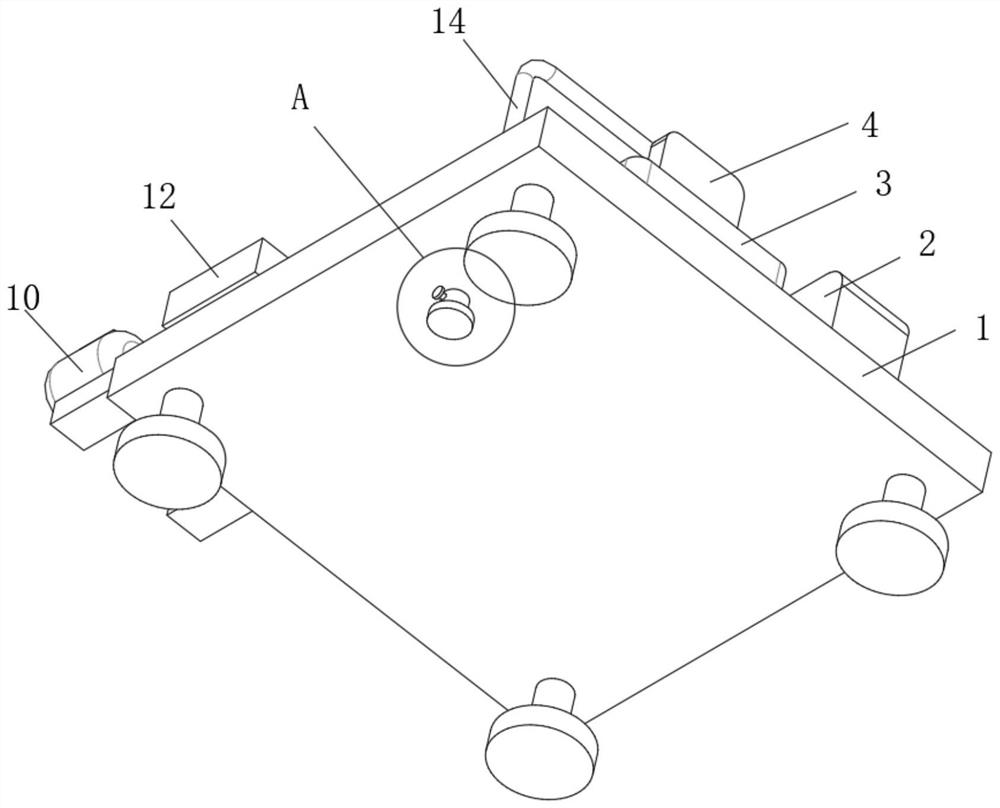
[0038] The first embodiment: as Figure 1-Figure 10 As shown, when testing the heat resistance performance, when the upper case 7 and the lower case 6 are separated, pull the pull rod 86 on the power connection mechanism 8, so that the two groups of power connection mechanisms 8 are far away, and place the resistor 9 in the On one side of the power connection mechanism 8, loosen the pull rod 86 to realize clamping and fixing, place the upper casing 7 above the lower casing 6, and install it with the installation mechanism 19, start the No. 1 air pump 10, and the No. 1 air pump 10 pumps in The gas enters the heating box 12 through the No. 3 pipe 17, starts the heating pipe 21 in the heating box 12, the gas heats up in the heating box 12 and enters the inside of the distribution mechanism 13 through the No. 1 pipe 15, and makes the high-temperature gas pass through The connecting pipe 14 enters the detection space surrounded by the upper casing 7 and the lower casing 6, and the r...

no. 2 example

[0042] The second embodiment: as Figure 1-Figure 7 As shown, the clamping sleeve 83 of the electrical connection mechanism 8 is sleeved in the arc groove on the top surface of the lower housing 6, and the fixed rod 81 and the No. 1 spring 82 fixedly installed on the side of the side plate 4 are sleeved in the clamping sleeve. In 83, the elastic effect of the No. 1 spring 82 is used to make the resistor 9 push the pull rod 86 and drive the clamping sleeve 83 to move when the resistor 9 is installed, so that the resistor 9 is effectively clamped between the two sets of clamping sleeves 83, and through the The end face of the clamping sleeve 83 is equipped with a connecting plate 85, and the connecting plate 85 is electrically connected to the connecting wire 18, so that the resistor 9 hovers between the lower casing 6 and the upper casing 7 after being clamped, and the outer surface of the resistor 9 Not in contact with the power connection mechanism 8, so that when hot air and...


PUM


Abstract

The invention belongs to the technical field of resistance detection equipment, and discloses a resistance heat resistance detection device for a high-temperature area of electronic equipment, the resistance heat resistance detection device comprises a base, a detection plate is fixedly mounted on the top surface of the base, a mounting seat is fixedly mounted on the top surface of the base, and a side plate is fixedly mounted on the top surface of the mounting seat. By changing the temperature of the environment where the resistor is located, the environment temperature change of electronic equipment in the actual resistor use environment is effectively simulated, alternating detection of the resistor in the high-temperature and low-temperature environment is carried out, and the heat resistance of the resistor in the high-temperature environment is detected under the condition that high-temperature air is continuously introduced; alternating detection of the resistor in high and low temperature environments is realized in cooperation with the distribution mechanism, the use performance of the resistor in actual use is effectively detected, the comprehensive index performance of resistor use is perfected and enriched, the resistor selection and matching effect of electronic equipment used in the high temperature environment is greatly improved, and the use effect of the electronic equipment in the high temperature environment is improved.

Description

technical field [0001] The invention belongs to the technical field of resistance detection equipment, in particular to a resistance heat resistance detection device used in high temperature areas of electronic equipment. Background technique [0002] With the rapid development of electronic technology, the requirements for electronic products are getting higher and higher, not only require excellent performance at room temperature, but also require normal and reliable work under high temperature conditions, for electronic equipment used in high temperature areas, for It is of great significance to conduct high-temperature reliability tests on resistors on electronic equipment. At present, high-temperature tests have been widely used in aerospace, communications, testing, weapon systems and other fields to detect and identify the comprehensive performance of electronic products in high-temperature environments. [0003] Existing resistance heat resistance detection devices u...

Claims


Application Information

Patent Timeline
IPC IPC(8): G01N25/00
CPCG01N25/00
Inventor 马建东王秋雨蒋多英马建平
Owner 深圳市东凌电子有限公司
Learn More