Power distribution cabinet convenient to assemble

A technology for power distribution cabinets and side panels, which is applied in substation/power distribution device shells, substation/switchgear panels/panels/desks, electrical components, etc., which can solve problems affecting work efficiency and inconvenient maintenance, and achieve improved disassembly Efficient, easy to transport, small footprint

Inactive Publication Date: 2022-03-18
江西俊朗电力装备有限公司
View PDF1 Cites 2 Cited by
  • Summary
  • Abstract
  • Description
  • Claims
  • Application Information

AI Technical Summary

Problems solved by technology

[0005] In order to overcome the shortcomings that the existing power distribution cabinets are all fixed by bolts, manual operation is required to tighten the screw, which affects work efficiency and is not easy to maintain. The technical problem of the present invention is to provide a stable structure and efficient assembly. Assembled distribution cabinet

Method used


Image

  • Power distribution cabinet convenient to assemble
  • Power distribution cabinet convenient to assemble
  • Power distribution cabinet convenient to assemble

Examples


Embodiment 1

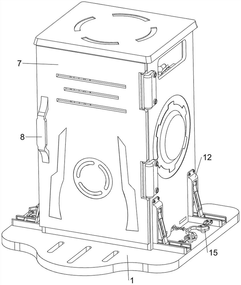
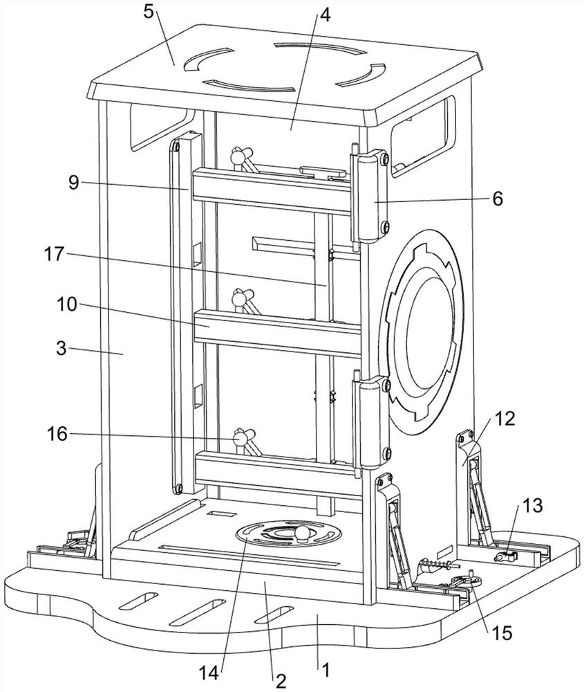
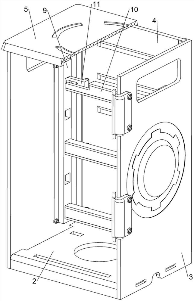
[0038] A power distribution cabinet that is easy to assemble, in Figure 1-3 As shown in , it includes bottom plate 1, support plate 2, side plate 3, baffle plate 4, top cover 5, connection plate 6, switch door 7, handle 8, support block 9, installation plate 10, card position block 11, card Positioning mechanism 12 and locking mechanism 13, support plate 2 is welded in the middle of the top of base plate 1, side plates 3 are slidingly provided on the left and right side walls of support plate 2, both side plates 3 are in contact with base plate 1, and the two side plates The baffle plate 4 is slidingly arranged between the rear sides, the baffle plate 4 is in contact with the bottom plate 1, and the baffle plate 4 can no longer be in contact with the bottom plate 1 when it moves upwards, and the top of the baffle plate 4 slides between the tops of the two side plates 3 There is a top cover 5, the top cover 5, the baffle plate 4 and the side plate 3 form a protective cabinet t...

Embodiment 2

[0043] On the basis of Example 1, in figure 2 , Figure 8 with Figure 9 Shown in , also includes reinforcement mechanism 14, and reinforcement mechanism 14 includes turntable 140, torsion spring 141, clamp block 142, connecting shaft 143 and second connection block 144, bottom plate 1 middle rotation type is provided with turntable 140, turntable 140 It is rotatably connected with the support plate 2, a torsion spring 141 is connected between the turntable 140 and the bottom plate 1, and the front and rear sides of the two fixed plates 120 are slidingly provided with blocks 142 for clamping the side plate 3. The connecting shafts 143 are all connected between the blocks 142, and the four blocks 142 are all slidably matched with the side plate 3 on the same side, and the four blocks 142 can be separated from the corresponding side plate 3 when moving in a direction close to the turntable 140. Both connecting shafts 143 are rotatably provided with a second connecting block 1...


PUM


Abstract

The invention relates to a power distribution cabinet, in particular to a power distribution cabinet convenient to assemble. The power distribution cabinet convenient to assemble is stable in structure and efficient to assemble. A power distribution cabinet convenient to assemble comprises a bottom plate, a supporting plate, side plates, a baffle, a top cover and the like, the supporting plate is arranged in the middle of the top of the bottom plate, the side plates are arranged on the left side wall and the right side wall of the supporting plate in a sliding mode, the two side plates are in contact fit with the bottom plate, the baffle is arranged between the rear sides of the two side plates in a sliding mode, and the baffle is in contact fit with the bottom plate. And top covers are arranged between the top of the baffle and the tops of the two side plates in a sliding manner. By separating the clamping blocks from the notches, the height of the mounting plate can be adjusted, instruments and devices can be conveniently mounted on the mounting plate, the instrument mounting device can be suitable for mounting work of instruments of different sizes, the side plates, the baffle and the top cover can be detached, the instrument mounting device is convenient to transport, the occupied area is small, and the instrument mounting device is not prone to damage in the transporting process.

Description

technical field [0001] The invention relates to a distribution cabinet, in particular to a distribution cabinet which is easy to assemble. Background technique [0002] The power distribution cabinet is a complete set of devices for centralized installation of switches, instruments and other equipment. It is a general name for the motor control center. Chemical processing is completed and then transported for use. [0003] The publication number is CN212085480U, which is an easy-to-assemble power distribution cabinet, including a base and a fan. The left and right sides of the lower end surface of the base are provided with self-locking rollers, and the bottom and base of the main body of the power distribution cabinet are provided with ventilation. and the lower side of the air vent is provided with a filter plate, the main body of the power distribution cabinet is provided with a bearing plate, and the upper end surface of the bearing plate is provided with a mounting hol...

Claims


Application Information

Patent Timeline
Patent Type & Authority Applications(China)
IPC IPC(8): H02B1/056H02B1/04H02B1/30H02B1/36
CPCH02B1/056H02B1/04H02B1/30H02B1/36
Inventor 李桂有
Owner 江西俊朗电力装备有限公司
Why Eureka
Try Eureka