Refrigeration system using non-azeotropic mixed refrigerant
A non-azeotropic mixing and refrigeration system technology, applied in refrigerators, refrigeration components, refrigeration and liquefaction, etc., can solve problems such as excessive cooling, and achieve the effect of improving the coefficient of performance
Pending Publication Date: 2022-03-18
LG ELECTRONICS INC
1 Cites 0 Cited by
AI-Extracted Technical Summary
Problems solved by technology
That is, simultaneous operation of cooling only the freezer and refrigerator is possible
Also, the refrigerating roo...
Method used
[0079] However, there are various methods for reducing irreversible losses due to heat exchange. A representative method is to configure a heat exchanger with counterflow. Counterflow heat exchangers can reduce irreversible losses by allowing the temperature difference between the moving fluids to be minimized.
[0086] In general refrigeration equipment, the temperature difference of the air passing through the inlet and outlet of the evaporator can reach 4°C to 10°C. In most cases, the temperature difference of the air is close to 4°C. Therefore, the glide temperature difference of the zeotropic mixed refrigerant can be kept higher than 4°C. It may be advantageous to maintain the glide temperature difference at least 4.1°C or higher, which is minimally higher than the temperature difference between the inlet and outlet of the evaporator. When the glide temperature difference of the non-azeotropic mixed refrigerant is less than 4.1° C., the thermal efficiency of the refrigeration cycle may decrease.
[0125] The difference in glide temperature of the non-azeotropic refrigerant mixture can be utilized so that the refrigerant flows into two evaporators connected in series. Therefore, irreversible loss caused by mixing of refrigerants having different properties can be reduced. Therefore, power consumption can be reduced.
[0135] The compressor suction pipe 170 connecting the second evaporator 160 to the compresso...
Abstract
A refrigeration system may include a compressor configured to compress a non-azeotropic mixed refrigerant; a condenser configured to condense the compressed non-azeotropic mixed refrigerant; a three-way valve configured to branch the non-azeotropic mixed refrigerant condensed by the condenser; a first evaporator configured to supply cold air to the first internal space; a second evaporator configured to supply cold air to the second internal space at a temperature higher than a temperature of the first internal space; and a capillary tube configured to expand the non-azeotropic mixed refrigerant branched by the three-way valve, and supply the expanded non-azeotropic mixed refrigerant to at least one of the first evaporator or the second evaporator. By utilizing the characteristics, an efficient refrigeration system using the non-azeotropic mixed refrigerant can be realized.
Application Domain
Mechanical apparatusCompression machines with several evaporators +1
Technology Topic
PhysicsRefrigerant +5
Image
Examples
- Experimental program(1)
Example Embodiment
[0039] Hereinafter, embodiments will be described with reference to the accompanying drawings. Embodiments are not limited to the embodiments discussed below, and those skilled in the art who understand the spirit thereof will be able to easily come up with other embodiments falling within the scope by adding, modifying, and deleting components. However, this also falls into its spirit.
[0040] First, a preferably applicable zeotropic mixed refrigerant is proposed. In the description related to the selection of the non-azeotropic mixed refrigerant, the content of the present disclosure is divided into technical elements and described in detail. First, the process of selecting the type of zeotropic mixed refrigerant will be described.
[0041] Selection of the type of zeotropic refrigerant mixture
[0042] Refrigerants to be mixed suitable for non-azeotropic mixed refrigerants are proposed. As the refrigerant to be mixed, a hydrocarbon-based (HC-based) refrigerant can be selected. Hydrocarbon-based refrigerants are environmentally friendly refrigerants having low ozone depletion potential (ODP) and low global warming potential (GWP). The criteria for selecting a refrigerant suitable for a zeotropic mixed refrigerant among hydrocarbon-based refrigerants can be summarized as follows.
[0043] First, from the perspective of compression work, when the difference between the condensation pressure (Pd or p1) and the evaporation pressure (Ps or p2) (pressure difference (△P)) is small, the compression work of the compressor is further reduced , which is good for efficiency. Therefore, a refrigerant with low condensing pressure and high evaporating pressure can be selected. However, considering the reliability of the compressor, an evaporation pressure of 50kPa or higher can be selected.
[0044] Second, from the viewpoint of utilization of production facilities, refrigerants that have been used in the past can be selected to be compatible with existing facilities and components. Third, from the viewpoint of the purchase cost of the refrigerant, it is possible to select a refrigerant that is available at low cost. Fourth, from a safety point of view, you can choose a refrigerant that is harmless to humans when the refrigerant leaks.
[0045] Fifth, from the viewpoint of reducing irreversible loss, it is desirable to reduce the temperature difference between the refrigerant and the cold air to improve the efficiency of the cycle. Sixth, from the perspective of handling, it is possible to choose a refrigerant that can be conveniently handled during work and can be easily injected by the handler.
[0046] The above criteria for selecting a refrigerant are applied in various ways in selecting a zeotropic mixed refrigerant.
[0047] Classification and selection of hydrocarbons
[0048] Based on evaporation temperature (Tv), candidate refrigerants suggested by the National Institute of Standards and Technology were classified into three groups (upper group, middle group, and lower group) in descending order of evaporation temperature. The density of the refrigerant becomes higher as the evaporation temperature increases.
[0049] A combination of candidate refrigerants capable of exhibiting an evaporation temperature of -20°C to -30°C suitable for the environment of the refrigeration equipment may be selected. Hereinafter, classification of candidate refrigerants will be described.
[0050] Candidate refrigerants were classified into three types based on boundary values of evaporation temperature (ie, -12°C and -50°C). Candidate refrigerants classified into three types are shown in Table 1. It can be seen that the classification of evaporation temperature varies greatly based on the boundary values.
[0051] [Table 1]
[0052]
[0053] Referring to Table 1, refrigerants that can be mixed as non-azeotropic mixed refrigerants can be selected and combined in each zone. First, which group is selected from the three groups will be described. There may be one case where the refrigerant is selected from three groups and three refrigerants are mixed, and three cases where the refrigerant is selected from two groups and two refrigerants are mixed.
[0054] When at least one refrigerant is selected from each of the three groups and the three or more refrigerants are mixed, the temperature rise and fall in the zeotropic mixed refrigerant may be excessive. In this case, the design of the refrigeration system can be difficult.
[0055] Therefore, a zeotropic mixed refrigerant can be obtained by selecting at least one refrigerant from each of the two groups. At least one refrigerant may be selected from each of the middle group and the lower group, from each of the upper group and the middle group, and from each of the upper group and the lower group. Among them, a composition in which at least one refrigerant selected from each of the above group and the middle group is mixed may be provided as a zeotropic mixed refrigerant.
[0056] When at least one refrigerant selected from each of the middle group and the lower group is mixed, the evaporation temperature of the refrigerant is too low. Therefore, in general refrigeration equipment, the difference between the internal temperature and the evaporation temperature of the refrigerant is too large. Therefore, the efficiency of the refrigeration cycle decreases and power consumption increases.
[0057] When at least one refrigerant selected from each of the upper group and the lower group is mixed, the difference in evaporation temperature between the at least two refrigerants is too large. Therefore, unless a special high-pressure environment is created, each refrigerant is classified into a liquid refrigerant and a gas refrigerant under actual use conditions. Therefore, it is difficult to inject at least two kinds of refrigerants together into the refrigerant tubes.
[0058] Select a hydrocarbon from the group of hydrocarbons
[0059] Which refrigerant is selected from the upper group and the middle group will be described below.
[0060] First, refrigerants selected from the above group will be described. At least one refrigerant selected from the above group may be used as the zeotropic mixed refrigerant.
[0061] Since isopentane and butadiene have relatively high evaporation temperatures, the internal temperature of the evaporator of the refrigeration equipment is limited and the refrigeration efficiency is reduced. Isobutane and n-butane can be used without changing the components of the currently used refrigeration cycle (such as the compressor of the refrigeration equipment). Therefore, their use is most desirable among the refrigerants included in the above group.
[0062] n-butane has less work of compression than isobutane, but has a low evaporation pressure (Ps), which may cause problems in reliability of the compressor. Therefore, isobutane can be selected from the above group. As described above, it is allowed to select at least one hydrocarbon from other hydrocarbons included in the above group.
[0063] Refrigerants selected from the middle group will be described below. At least one refrigerant selected from the intermediate group may be used in the zeotropic mixed refrigerant.
[0064] Since the pressure difference (△P) of propadiene is smaller than that of propane, the efficiency is high. However, propadiene is expensive and can be harmful to the respiratory system and skin when inhaled by humans due to leakage. The pressure difference of propylene is greater than that of propane, so the compression work of the compressor increases.
[0065] Therefore, propane can be selected from the intermediate group. As described above, at least one selected from other hydrocarbons included in the intermediate group is allowed.
[0066] For reference, isobutane may also be referred to as R600a, and propane may also be referred to as R290. Although isobutane and propane can be chosen, other hydrocarbons belonging to the same group can also be used to obtain the properties of zeotropic mixed refrigerants, even if not specifically mentioned in the following description. For example, compositions other than isobutane and propane may be used if a similar glide temperature difference of a zeotropic mixed refrigerant can be obtained.
[0067] Selection of the proportion of the selected hydrocarbon refrigerant considering the power consumption of the compression work
[0068] Isobutane was selected from the upper group and propane was selected from the middle group as the refrigerant to be mixed in the zeotropic mixed refrigerant. The ratio of refrigerants to be mixed in the zeotropic mixed refrigerant can be selected as follows.
[0069] The power consumption of the compressor, which is the main energy source of the refrigeration system, depends on the pressure difference. In other words, as the pressure difference increases, more compression work needs to be consumed. As the work of compression increases, the efficiency of the cycle further decreases.
[0070] The pressure difference (ΔP) of isobutane is less than that of propane. Therefore, it is possible to provide the zeotropic mixed refrigerant with a weight ratio of 50% or more of isobutane and 50% or less of propane.
[0071] In the case of a composition in which the zeotropic mixed refrigerant includes isobutane and propane mixed in a ratio of 5:5, the condensation pressure was 745.3 kPa, the evaporation pressure was 120.5 kPa, and the pressure difference was 624.7 kPa. In the case of a composition in which the zeotropic mixed refrigerant is substantially isobutane with a very small amount of propane, the condensation pressure is 393.4 kPa, the evaporation pressure is 53.5 kPa, and the pressure difference is 340.0 Pa.
[0072] Under the ISO power consumption measurement conditions, the pressure is obtained by measuring the average value when the compressor is turned on. All values related to the composition of zeotropic mixed refrigerants were obtained under the same conditions.
[0073] The ranges of the condensation pressure, evaporation pressure and pressure difference of the non-azeotropic mixed refrigerant can be known using the mixing ratio of isobutane to propane, which can reduce the compression work as described above.
[0074] Selection of the proportion of the selected hydrocarbon refrigerant taking into account the irreversible losses of the evaporator
[0075] As described above, the zeotropic mixed refrigerant has a glide temperature difference (GTD) at the time of phase transition. Using the glide temperature difference, evaporators can be installed sequentially in the freezer and refrigerator to provide an appropriate temperature atmosphere for each compartment. According to the glide temperature difference, the temperature difference between air and evaporated refrigerant in each evaporator can be reduced, thereby reducing irreversibility that occurs during heat exchange. The reduction of irreversible loss can reduce the loss of refrigeration system.
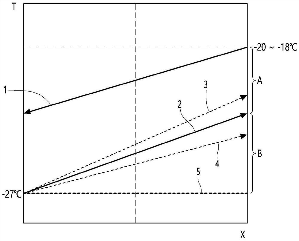
[0076] figure 1 is a schematic temperature diagram of a zeotropic mixture of refrigerant and air in a counterflow evaporator. exist figure 1 In , the horizontal axis represents progress distance, and air and zeotropic mixed refrigerant move in opposite directions indicated by arrows. exist figure 1 In , the vertical axis represents temperature. refer to figure 1, 1 is the line for air, 2 is the line for non-azeotropic refrigerant mixture, 3 is the line for temperature increase of non-azeotropic refrigerant mixture, 4 is the line for temperature decrease of non-azeotropic refrigerant mixture , and 5 is the line for a single refrigerant.
[0077] For example, referring to line 1 for air, the temperature of the air may drop from a range of -20°C to -18°C, and the air may pass through the evaporator. Referring to line 2 of the zeotropic mixed refrigerant, the temperature of the zeotropic mixed refrigerant can be raised from -27° C., and the zeotropic mixed refrigerant can pass through the evaporator. The glide temperature difference of zeotropic refrigerant mixtures can vary depending on the ratio of isobutane to propane. When the glide temperature difference increases, the line 2 of the non-azeotropic mixed refrigerant may move toward the line 3 of the temperature increase of the non-azeotropic mixed refrigerant. When the glide temperature difference decreases, the line 2 of the non-azeotropic mixed refrigerant may move toward the line 4 of the temperature drop of the non-azeotropic mixed refrigerant. For reference, since there is no phase change in a single refrigerant, there is no temperature change in line 5 for a single refrigerant.
[0078] Due to the temperature difference that exists between the two interfaces where heat exchange occurs, irreversible losses cannot be avoided when heat exchange occurs. For example, when there is no temperature difference between the interface of two objects exchanging heat with each other, there is no irreversible loss, but no heat exchange occurs.
[0079] However, there are various methods for reducing irreversible losses due to heat exchange. A representative method is to configure a heat exchanger with counterflow. Counterflow heat exchangers can reduce irreversible losses by allowing the temperature difference between the moving fluids to be minimized.
[0080] In the case of an evaporator using a zeotropic refrigerant mixture, the heat exchanger can be configured as figure 1 reverse flow shown. When the temperature of the non-azeotropic mixed refrigerant increases due to the glide temperature difference during evaporation, the temperature difference between the air and the non-azeotropic mixed refrigerant may decrease. When the glide temperature difference of the non-azeotropic mixed refrigerant and the temperature difference of the air are reduced, irreversible losses can be reduced, and the efficiency of the refrigeration cycle can be improved.
[0081] The glide temperature difference of zeotropic refrigerant mixtures may not increase infinitely due to refrigerant limitations. In addition, when the glide temperature difference of the non-azeotropic mixed refrigerant changes, the glide temperature difference of the cold air changes. Therefore, the size of the evaporator changes and the overall efficiency of the refrigeration cycle is affected. For example, when the glide temperature difference increases, the inlet temperature of the refrigerant decreases or the outlet temperature of the refrigerant overheats, thereby reducing the efficiency of the refrigeration cycle.
[0082] On the other hand, if the size of the heat exchanger is infinitely large, the glide temperature difference of the zeotropic mixed refrigerant and the temperature difference of the air can converge to zero. However, in consideration of mass-producibility and cost reduction of heat exchangers, in the case of general refrigeration equipment, the difference in glide temperature of the zeotropic mixed refrigerant and the temperature difference of air is about 3°C to 4°C.
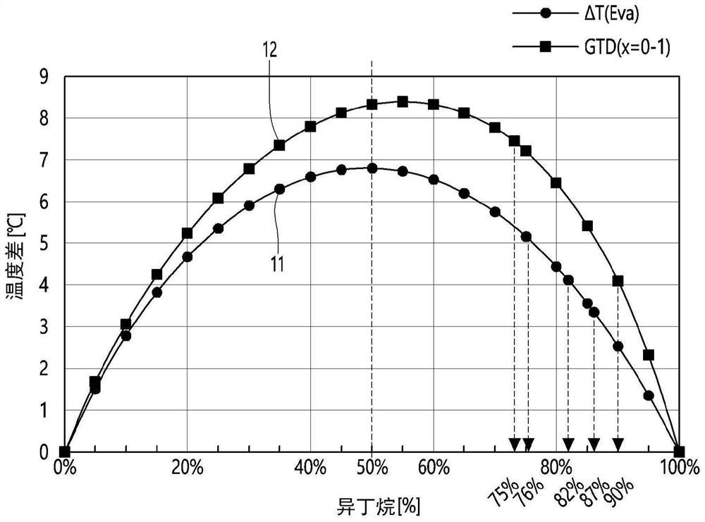
[0083] figure 2 It is a graph showing the temperature difference between the inlet and outlet of the evaporator and the glide temperature difference of the zeotropic mixed refrigerant according to the composition of isobutane and propane. The horizontal axis represents the content of isobutane, and the vertical axis represents the temperature difference.
[0084] refer to figure 2 , when each of isobutane and propane is contained at 100%, there is no temperature change while each of isobutane and propane undergoes evaporation as a single refrigerant. When isobutane and propane are mixed, there is a glide temperature difference of the non-azeotropic mixed refrigerant and a temperature difference between the inlet and outlet of the evaporator. The temperature difference 11 between the inlet and the outlet of the evaporator is smaller than the glide temperature difference 12 of the non-azeotropic mixed refrigerant. This can be caused by incomplete heat transfer between the refrigerant and the air.
[0085] When the glide temperature difference of the non-azeotropic mixed refrigerant is greater than the temperature difference between the inlet and outlet of the evaporator, the characteristics of the non-azeotropic mixed refrigerant can be well utilized. Also, it is advantageous from the viewpoint of reducing irreversibility in heat exchange and improving the efficiency of the refrigeration cycle. Also, the glide temperature difference of the zeotropic mixed refrigerant may be greater than the temperature difference of the air passing through the evaporator.
[0086] In general refrigeration equipment, the temperature difference between the inlet and outlet of the evaporator can reach 4°C to 10°C. In most cases, the temperature difference of the air is close to 4°C. Therefore, the glide temperature difference of the zeotropic mixed refrigerant can be kept higher than 4°C. It may be advantageous to maintain the glide temperature difference at least 4.1°C or higher, which is minimally higher than the temperature difference between the inlet and outlet of the evaporator. When the glide temperature difference of the non-azeotropic mixed refrigerant is less than 4.1° C., the thermal efficiency of the refrigeration cycle may decrease.
[0087] On the contrary, when the glide temperature difference of the zeotropic mixed refrigerant is greater than 4.1° C., the temperature difference between the refrigerant and air at the outlet side of the refrigerant decreases, the irreversibility decreases, and the thermal efficiency of the refrigeration cycle increases. The reduced temperature difference between the refrigerant and the air at the outlet side of the refrigerant means that figure 1 The line 2 of the non-azeotropic refrigerant mixture moves toward the line 3 of the temperature increase of the non-azeotropic refrigerant mixture.
[0088] exist figure 2 Among them, when the glide temperature difference of the non-azeotropic mixed refrigerant is 4.1°C, the isobutane is 90%, and when the glide temperature difference of the non-azeotropic mixed refrigerant is greater than 4.1°C, the isobutane is less than 90% %. In order to minimize the compression work of the compressor, isobutane can be 50% or more.
[0089] As a result, the weight ratio of the zeotropic mixed refrigerant provided with isobutane and propane may be as shown in Equation 1.
[0090] [mathematical formula 1]
[0091] 50%≤isobutane≤90%
[0092] Propane is the remaining component or other components in the weight ratio of the zeotropic mixture refrigerant.
[0093] When the glide temperature difference of the non-azeotropic mixed refrigerant increases, the irreversible loss can be reduced. However, when the glide temperature difference is too large, the size of the evaporator becomes too large in order to ensure a sufficient heat exchange path between the refrigerant and the air. When the evaporator applied to general household refrigeration equipment is designed to have a capacity of 200W or less, the space inside the refrigeration equipment can be secured. Therefore, the glide temperature difference of the zeotropic mixed refrigerant can be limited to 7.2°C or less.
[0094] In addition, when the glide temperature difference of the non-azeotropic mixed refrigerant is too large, the temperature of the inlet of the evaporator may be too low or the outlet of the evaporator outlet may be overheated too quickly based on the non-azeotropic mixed refrigerant. The available area of the evaporator may be reduced, and the efficiency of heat exchange may be reduced.
[0095] At the outlet of the evaporator, the temperature of the zeotropic mixed refrigerant must be higher than the temperature of the air introduced into the evaporator. Otherwise, the efficiency of the heat exchanger decreases due to the inversion of the temperatures of the refrigerant and the air. When this condition is not met, the efficiency of the refrigeration system may decrease.
[0096] exist figure 2 Among them, when the glide temperature difference of the non-azeotropic mixed refrigerant is 7.2°C, the isobutane is 75%, and when the glide temperature difference of the non-azeotropic mixed refrigerant is less than 7.2°C, the isobutane is more than 75%. %. As a result, considering this condition together with the condition of Formula 1, the weight ratio of the zeotropic mixed refrigerant provided with isobutane and propane can be as shown in Formula 2.
[0097] [mathematical formula 2]
[0098] 75%≤isobutane≤90%
[0099] Propane is the remaining component or other components in the weight ratio of the zeotropic mixture refrigerant.
[0100] The selection of the proportion of the selected hydrocarbon refrigerant considering the compatibility of the production facility and components
[0101] The temperature difference between the inlet and outlet of the evaporator of general refrigeration equipment can be set at 3°C to 5°C. This is due to various factors such as the components of the refrigeration plant, the internal volume of the mechanical room, the heat capacity of each component and the size of the fan. when in figure 2 When the composition ratio of the zeotropic mixed refrigerant is found to provide the temperature of the inlet and outlet of the evaporator (ie, 3° C. to 5° C.), it can be seen that isobutane is between 76% and 87%.
[0102] As a result of the above discussion, a zeotropic mixed refrigerant satisfying all the above conditions can be expressed as Equation 3.
[0103] [mathematical formula 3]
[0104] 76%≤isobutane≤87%
[0105] Propane is the remaining component or other components in the weight ratio of the zeotropic mixture refrigerant.
[0106] Proportion of hydrocarbon refrigerant to be finally applied
[0107] The isobutane application range that can be selected based on the above various criteria can be determined to be 81% to 82%, which is the middle range of Equation 3. Propane can occupy the remainder or components of the zeotropic mixture refrigerant.
[0108] The case of using only isobutane was compared with the case of using a zeotropic mixed refrigerant in which 85% of isobutane and 15% of propane were used. In both cases, the evaporators are configured in parallel to form a cycle of the refrigeration system.
[0109] The experimental conditions were -29°C and -15°C, respectively, and the inlet temperature of the compressor was 25°C. Due to the difference in refrigerant, when only isobutane is used, the temperature of the condenser is 31°C, while when using azeotropic mixed refrigerant, the temperature of the condenser is 29°C.
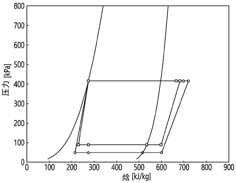
[0110] Figure 3A and Figure 3B is a table for comparing refrigeration cycles in each case. Figure 3A is a graph showing the refrigeration cycle when only isobutane is used. Figure 3B is a graph showing a refrigeration cycle when a non-azeotropic refrigerant mixture is used.
[0111] in accordance with Figure 3A-Figure 3B In the experiments, it can be seen that the improvement of the coefficient of performance is about 4.5% when the zeotropic refrigerant mixture is used.
[0112] Figure 4 is a diagram showing a refrigeration device according to an embodiment. refer to Figure 4 , The cooling device according to the embodiment may include a machine room 31 , a freezing room 32 and a refrigerating room 33 . The refrigeration equipment forms a refrigeration cycle using a non-azeotropic mixed refrigerant. In the refrigeration cycle, a compressor 21 compressing refrigerant, an expander 22 expanding compressed refrigerant, a condenser 23 condensing expanded refrigerant, and first and second evaporators 24 and 25 may be included.
[0113] The compressor 21 , the expander 22 and the condenser 23 may be disposed in the machine room 31 . The first evaporator 24 may be disposed in the freezing compartment 32 . The second evaporator 25 may be disposed in the refrigerator compartment 33 . Freezers and refrigerators may be referred to as "interior spaces".
[0114] The temperature of the non-azeotropic mixed refrigerant in the first evaporator 24 may be lower than that in the second evaporator 25 . When the first evaporator 24 is placed in the freezer compartment 32, the refrigeration system can more properly operate in the compartment of the refrigeration equipment. Therefore, irreversible losses can be further reduced in the evaporation operation of the evaporator.
[0115] Figure 5 is a schematic diagram of a refrigeration system suitable for refrigeration equipment according to an embodiment. refer to Figure 5 , The refrigeration system according to this embodiment may include a compressor 110 compressing refrigerant, a condenser 120 condensing the compressed refrigerant, and evaporators 150 and 160 evaporating refrigerant condensed by the condenser 120 . Refrigerant evaporated by the evaporators 150 and 160 may be circulated to the compressor 110 .
[0116] The evaporators 150 and 160 may include a first evaporator 150 capable of supplying cool air to the freezing compartment and a second evaporator 160 capable of supplying cool air to the refrigerating compartment. A three-way valve 130 capable of branching and supplying condensed refrigerant to the evaporators 150 and 160 may also be provided. The three-way valve 130 may selectively supply the refrigerant supplied from the condenser 120 to the first evaporator 150 or the second evaporator 160 . The three-way valve 130 may be a multi-way valve that branches the introduced refrigerant to at least two positions. When the three-way valve 130 branches the refrigerant in multiple directions, the three-way valve 130 may also be called a 'multi-way valve'.
[0117] The refrigerant heat-exchanged in the first evaporator 150 may be supplied to the second evaporator 160 . The refrigerant may be a non-azeotropic mixed refrigerant, and the temperature of the refrigerant may increase during evaporation. The first evaporator 150 may evaporate refrigerant at a lower temperature than the second evaporator 160 . Accordingly, the first evaporator 150 may be more suitable for supplying cool air to the freezing compartment, and the second evaporator 160 may be more suitable for supplying cool air to the refrigerating compartment.
[0118] The first evaporator 150 and the second evaporator 160 may be connected in series based on refrigerant flow. These advantages are remarkable compared with the case of using a single refrigerant or an azeotropic mixture refrigerant.
[0119] The advantages of the zeotropic mixed refrigerant when two evaporators are used in a single compressor will be described below.
[0120] First, a refrigeration system using two evaporators in a single compressor (hereinafter, simply referred to as "1-compression 2-evaporation system") can use a single refrigerant or an azeotropic mixed refrigerant whose temperature does not change during evaporation . The evaporator may include a refrigerating chamber evaporator supplying cool air to the refrigerating chamber and a freezing chamber evaporator supplying cool air to the freezing chamber.
[0121] In this case, when the two evaporators are connected in parallel, the refrigerant concentrates in the evaporator of the freezing chamber, which increases the irreversible loss and is difficult to control. On the contrary, when two evaporators are connected in series, the thermal insulation load in the freezing compartment is large, and therefore, the refrigerant must be supplied to the freezing compartment evaporator after passing through the refrigerating compartment evaporator. This is because the refrigerant must remain in the freezer evaporator for a long time in order to cope with the thermal insulation load of the freezer.
[0122] A three-way valve can be installed upstream of the refrigerating room evaporator. According to the three-way valve, refrigerant may be supplied to the freezing chamber evaporator without passing through the refrigerating chamber evaporator. In this way, overcooling of the refrigerating room corresponding to the refrigerating room evaporator can be prevented. This may be referred to as a "series bypass 1-compression 2-evaporation system".
[0123] The series bypass 1-compression 2-evaporation system is difficult to precisely control because the flow rate control of the refrigerant corresponding to the inner space and the intermittent control of the three-way valve corresponding to the change in the thermal insulation load of the refrigerating room and the freezing room are continuously required . In addition, when refrigerants of different states passing through different channels are continuously mixed, irreversible losses increase and power consumption increases.
[0124] As a solution to this problem, a zeotropic mixed refrigerant can be used in the 1-compression 2-evaporation system. The temperature of the zeotropic mixed refrigerant increases during evaporation. Using this property, the refrigerant may be supplied to the refrigerating chamber evaporator after passing through the freezing chamber evaporator. In this case, when the non-azeotropic mixed refrigerant is evaporated, cool air may be supplied to the freezer compartment at a first temperature corresponding to the freezer compartment temperature, and the cool air may be supplied at a second temperature corresponding to the freezer compartment temperature. Supplied to the freezer. The second temperature may be higher than the first temperature.
[0125] The difference in glide temperature of the non-azeotropic mixed refrigerant can be utilized so that the refrigerant flows into two evaporators connected in series. Therefore, irreversible loss caused by mixing of refrigerants having different properties can be reduced. Therefore, power consumption can be reduced.
[0126] The refrigeration system according to this embodiment may be referred to as a “series bypass 1-compression 2-evaporation” system in which the three-way valve 130 is located upstream of the first evaporator 150 and the second evaporator 160 . Due to the three-way valve 130 , the refrigerant may be supplied to both the evaporators 150 and 160 , or the refrigerant may bypass the first evaporator 150 and may be supplied to only the second evaporator 160 . In other words, the individual operation of the refrigerator ( Figure 5 in flow B) and the simultaneous operation of the refrigerator and freezer ( Figure 5 Flow A) in is possible.
[0127] The individual operation of the freezer reduces the frequency of the compressor and thus the capacity of the freezer relative to the simultaneous operation of the refrigerator and the freezer. Accordingly, the operation of the freezing chamber may be performed solely by evaporating all of the refrigerant in the first evaporator 150 corresponding to the freezing chamber. The refrigerator fan can be turned off by another method or a combination of methods.
[0128] In all the modes in which the refrigerating compartment is operated alone, the refrigerating and freezing compartments are simultaneously operated, and the freezing compartment is operated independently, the temperature of the zeotropic mixed refrigerant in the second evaporator 160 corresponding to the refrigerating compartment increases, and therefore, the influence on the refrigerating compartment can be reduced. Concerns about overcooling in refrigerators. The temperature during evaporation is the same when using a single refrigerant or an azeotropic mixture. Therefore, supercooling in the second evaporator 160 can be avoided.
[0129] The first capillary 140 may be disposed in a connection channel of the first evaporator 150 among the discharge sides of the three-way valve 130 . The second capillary 145 may be disposed in a connection channel of the second evaporator 160 in the discharge side of the three-way valve 130 . Each of capillaries 140 and 145 may be referred to as an "expander."
[0130] The first capillary 140 may expand the non-azeotropic mixed refrigerant to supply the refrigerant to the first evaporator 150 . The second capillary 145 may expand the non-azeotropic mixed refrigerant to supply the refrigerant to the second evaporator 160 .
[0131] A refrigerant outlet side of the first evaporator 150 may be connected to a refrigerant inlet side of the second evaporator 160 . A refrigerant outlet side of the first evaporator 150 may be connected to a refrigerant outlet side of the second capillary tube 145 .
[0132] The check valve 155 may be provided in a connecting pipe between the first evaporator 150 and the second evaporator 160 , that is, immediately downstream of the first evaporator 150 . The check valve 155 may allow refrigerant to flow from the first evaporator 150 to the second evaporator 160 and may not allow back flow in the opposite direction. Therefore, when switching from the simultaneous operation of the freezing chamber and the refrigerating chamber to the individual operation of the refrigerating chamber, the backflow of the refrigerant can be prevented.
[0133] A gas-liquid separator may not be properly installed in the connection pipe between the first evaporator 150 and the second evaporator 160 . This is because sufficient cooling power may not be supplied to the second evaporator 160 if only gas passes through the zeotropic mixed refrigerant that is only partially evaporated in the first evaporator 150 . In other words, the zeotropic mixed refrigerant may not be able to maintain the mixing ratio of the two refrigerants in the liquid and gas phases.
[0134] A gas-liquid separator 165 may be disposed on an outlet side of the second evaporator 160 . The gas-liquid separator 165 allows only gas refrigerant to be discharged to the compressor 110, thereby preventing damage and noise of the compressor 110 and improving efficiency.
[0135] The compressor suction pipe 170 connecting the second evaporator 160 to the compressor 110 and the capillary pipes 140 and 145 may exchange heat with each other. Accordingly, heat of the capillary tubes 140 and 145 may be transferred to the compressor suction pipe 170 so that the refrigerant introduced into the compressor 110 may maintain a gaseous state. Cool air from the compressor suction pipe 170 may be delivered to the capillary tubes 140 and 145 to prevent loss of cool air and reduce power consumption.
[0136] The compressor suction tube 170 may be in heat exchange with at least one of the capillary tubes 140 and 145 . The compressor suction pipe 170 and the first capillary tube 140 may exchange heat with each other during simultaneous operation of the freezing chamber and the refrigerating chamber and the single operation of the freezing chamber. The compressor suction pipe 170 and the second capillary pipe 145 may exchange heat with each other when the refrigerating chamber is independently operated. Therefore, cold air loss can be reduced in each mode, and the efficiency of the refrigeration cycle can be improved.
[0137] Compressor suction tube 170 may be in heat exchange with both capillary tubes 140 and 145 . Therefore, cooling air loss can be reduced in all operating modes. The compressor suction pipe 170, the first capillary tube 140, and the second capillary tube 145 may be disposed at positions adjacent to each other to exchange heat with each other.
[0138] The series bypass 1-compression 2-evaporation system has at least the following advantages. First, the glide temperature difference of the non-azeotropic mixed refrigerant is provided in the order of the freezer and the refrigerator, thereby reducing irreversible losses and reducing power consumption. Second, the individual operation of the refrigerating chamber, the individual operation of the freezing chamber, and the simultaneous operation of the freezing chamber and the refrigerating chamber can all be performed stably.
[0139] As the refrigerant of the example, a zeotropic mixed refrigerant whose temperature increases during evaporation is used. Therefore, the temperature at the outlet side of the capillary tubes 140 and 145 may be higher than the temperature at the outlet side of the second evaporator 160 . Due to this, a heat exchange reversal phenomenon may occur. The heat exchange reversal phenomenon will be described below.
[0140] Image 6 is a schematic diagram of the evaporator and capillary showing the temperature at each point. will refer to Image 6 Describes the temperature inversion of a regenerative heat exchanger with a zeotropic refrigerant mixture.
[0141] Image 6 A first evaporator 150 , a second evaporator 160 and a regenerative heat exchanger 180 are shown in which heat exchange is performed between the compressor suction line 170 and the capillary tubes 140 and 145 . Image 6 Simultaneous operation of the freezer and refrigerator is shown.
[0142] Each point on the graph is marked with a P, the first number 1 after P indicates the inlet side of the first capillary, and the first number 2 after P indicates the inlet side of the compressor suction tube. The second number after the P indicates the order of progression.
[0143] The refrigerant introduced through the inlet of the first capillary tube 140 flows through the passages of points P11, P12, P13, and P14. The refrigerant introduced through the inlet of the compressor suction pipe 170 flows through the passages of points P21 and P22. The regenerative heat exchanger 180 may correspond to a region indicated by an arrow.
[0144] The temperature of the refrigerant flowing through the first capillary tube 140 in the region of the regenerative heat exchanger 180 drops from 31°C to -27°C (P11 -> P12). The temperature of the refrigerant flowing through the compressor suction pipe 170 in the region of the regenerative heat exchanger 180 rises from 0°C to 25°C (P21 -> P22). In the region of the regenerative heat exchanger 180 , a heat exchange reversal zone can thus occur in which the heat exchange between the capillary tube and the compressor suction line is reversed.
[0145] The heat exchange inversion area may be a factor that reduces heat exchange efficiency and increases power consumption. In the drawing, a vertically extending arrow schematically indicates a region in which the regenerative heat exchanger 180 is disposed.
[0146] The refrigerant passing through the point P12 may pass through the first evaporator 150 . When the refrigerant passes through the first evaporator 150 , the refrigerant is discharged from the point P13 at -20° C. and introduced into the second evaporator 160 . The refrigerant further evaporated by the second evaporator 160 is discharged from a point P14 at the outlet side of the second evaporator 160 at 0°C. As the same point, the point P14 and the point P21 may be 0°C.
[0147] Figure 7 is a schematic diagram of the temperature change in the refrigerant tubes in a regenerative heat exchanger and in the compressor suction tube. refer to Figure 7, the direction of heat exchange is reversed at point T. It can be seen that the heat exchange reversal region is after point T based on the direction of progress of the capillary.
[0148] In the heat exchange reversal zone, cool air from the capillary tube is passed towards the compressor suction tube. This phenomenon leads to heat exchange losses in the evaporator and should therefore be avoided.
[0149] Refrigeration systems can be reconfigured to remove heat exchange reversal zones, but this is difficult in terms of production facilities and common use of components. Hereinafter, a structure in which the heat exchange inversion region itself disappears in the regenerative heat exchanger will be described.
[0150] Figure 8 is a partial view of the refrigeration system with the regenerative heat exchanger enlarged. refer to Figure 8 , the regenerative heat exchanger 180 is shown in dashed lines. In a regenerative heat exchanger (SLHX: Suction Line Heat Exchanger), heat exchange can be performed in such a way that the capillary tube and the compressor suction tube contact each other or are adjacent to each other.
[0151] Under the control of the three-way valve 130 , refrigerant may flow into at least one of the first capillary tube 140 or the second capillary tube 145 . In the drawing, the refrigerant passing through the capillary tubes 140 and 145 may flow from top to bottom, that is, flow downward. Refrigerant discharged from the second evaporator 160 may flow through the compressor suction pipe 170 . In the drawing, the refrigerant flowing through the compressor suction pipe 170 may flow from bottom to top, that is, upward. Since the drawings are for ease of understanding, directions may be left and right.
[0152] The refrigerant flowing through the capillary tube and the refrigerant flowing through the compressor suction pipe flow countercurrently and exchange heat with each other. As mentioned above, a heat exchange reversal zone may occur in the regenerative heat exchanger 180 . Therefore, for the heat exchange reversal region, the refrigerant in the capillary tube and the refrigerant in the compressor suction tube may not exchange heat with each other.
[0153] Based on the drawings, the regenerative heat exchanger 180 forms a heat exchange area A1 in which heat exchange is performed at an upper portion of point T and a shield area A2 in which heat exchange is performed at point T The heat exchange at the lower part is shielded. The heat exchange area A1 may be the geometrical area from point T to the three-way valve. Shielded area A2 may be the geometrical area from point T to the evaporator.
[0154] The temperature at point T may fluctuate depending on the operating conditions of the cycle of the refrigeration system. The temperature at point T may be in the range of -5°C to 5°C.
[0155] The tube length L1 of the shielded area A2 may be about 1 m. Point T can be placed about 1 m from the outlet of the capillary and the inlet of the compressor suction tube. That is, the shielded area may be included within about 1 m or less from the outlet of the capillary tube and the inlet of the compressor suction tube.
[0156] In shielded area A2, the two pipes may not be in contact with each other in order to shield the heat exchange between the outlet of the capillary and the compressor suction pipe. For example, two pipes may not be welded together. In contrast, in the heat exchange area A1, two pipes may be brought into contact with each other by a method such as welding. However, in order to allow uniform heat exchange to be performed in the regenerative heat exchanger, indirect heat exchange with low heat exchange performance may be performed. In this case, it may be advantageous to prevent all pipes from contacting each other by means such as welding.
[0157] Due to the glide temperature difference of the non-azeotropic mixed refrigerant, not only the heat exchange reversal area occurs in the series bypass 1-compression 2-evaporation system, but also the heat exchange reversal occurs in the parallel 1-compression 2-evaporation system area. Therefore, the shielded area A2 may be provided in a regenerative heat exchanger of a refrigeration system using a zeotropic mixed refrigerant. The parallel 1-compression 2-evaporation system may refer to a system in which an evaporator supplying cool air to the freezer compartment and an evaporator supplying cool air to the freezer compartment are connected in parallel to supply cool air to the freezer compartment and cold room.
[0158] will refer to Figure 9 and Figure 10 depicts the generation of heat exchange reversal regions in a parallel 1-compression 2-evaporation system.
[0159] Figure 9 is a schematic diagram of the evaporator and capillary in a parallel 1-compression 2-evaporation system. Figure 10A is a temperature graph illustrating the heat exchange inversion region in a parallel 1-compression 2-evaporation system when using a single refrigerant. Figure 10B is a temperature graph illustrating the heat exchange inversion region in a parallel 1-compression 2-evaporation system when a zeotropic mixed refrigerant is used.
[0160] refer to Figure 9 , the parallel 1-compression 2-evaporation system may include: a refrigerant supplier 190 that branches the condensed refrigerant to two evaporators; and a first evaporator 150 and a second evaporator 160 , which evaporates the refrigerant supplied from the refrigerant supplier 190 and supplies cool air. The first evaporator 150 may be an evaporator supplying cool air to the freezing compartment, and the second evaporator 160 may be an evaporator supplying cool air to the refrigerating compartment.
[0161] Since the refrigerant is a non-azeotropic mixed refrigerant, the temperature of the non-azeotropic mixed refrigerant increases due to a glide temperature difference during evaporation. Therefore, the shielding area A2 may be provided in the regenerative heat exchanger 180 .
[0162] It can be seen that in Figure 10A There is no heat exchange inversion region in , but in Figure 10B The heat exchange reversal region appears in the . As a result, in the case of a refrigeration system provided with a zeotropic mixed refrigerant and a regenerative heat exchanger, a shielded area is provided in the regenerative heat exchanger, thereby reducing power consumption.
[0163] Industrial Applicability
[0164] According to the embodiments disclosed herein, when a zeotropic mixed refrigerant is used, it is possible to provide a refrigeration system implementing various operation modes and improving a coefficient of performance.
PUM


Description & Claims & Application Information
We can also present the details of the Description, Claims and Application information to help users get a comprehensive understanding of the technical details of the patent, such as background art, summary of invention, brief description of drawings, description of embodiments, and other original content. On the other hand, users can also determine the specific scope of protection of the technology through the list of claims; as well as understand the changes in the life cycle of the technology with the presentation of the patent timeline. Login to view more.