Condenser for refrigerator

A technology for condensers and refrigerators, which is applied to evaporators/condensers, household refrigerators, and household refrigeration devices. It can solve problems such as excessive pressure drop, and achieve the goals of reducing heat exchange area, saving materials, and reducing costs. Effect

Inactive Publication Date: 2005-05-18
TSINGHUA UNIV
View PDF1 Cites 11 Cited by
  • Summary
  • Abstract
  • Description
  • Claims
  • Application Information

AI Technical Summary

Problems solved by technology

[0005] Aiming at the deficiencies and defects of the prior art, the object of the present invention is to provide a condenser for refrigerators to overcome the disadvantage of excessive pressure drop in the condensing process of the existing disc condenser, so that it has the advantages of simple structure, low cost and easy replacement. Advantages of higher thermal efficiency

Method used


Image

  • Condenser for refrigerator
  • Condenser for refrigerator

Examples


Embodiment Construction

[0010] The specific structure of the present invention will be further described below in conjunction with the accompanying drawings.

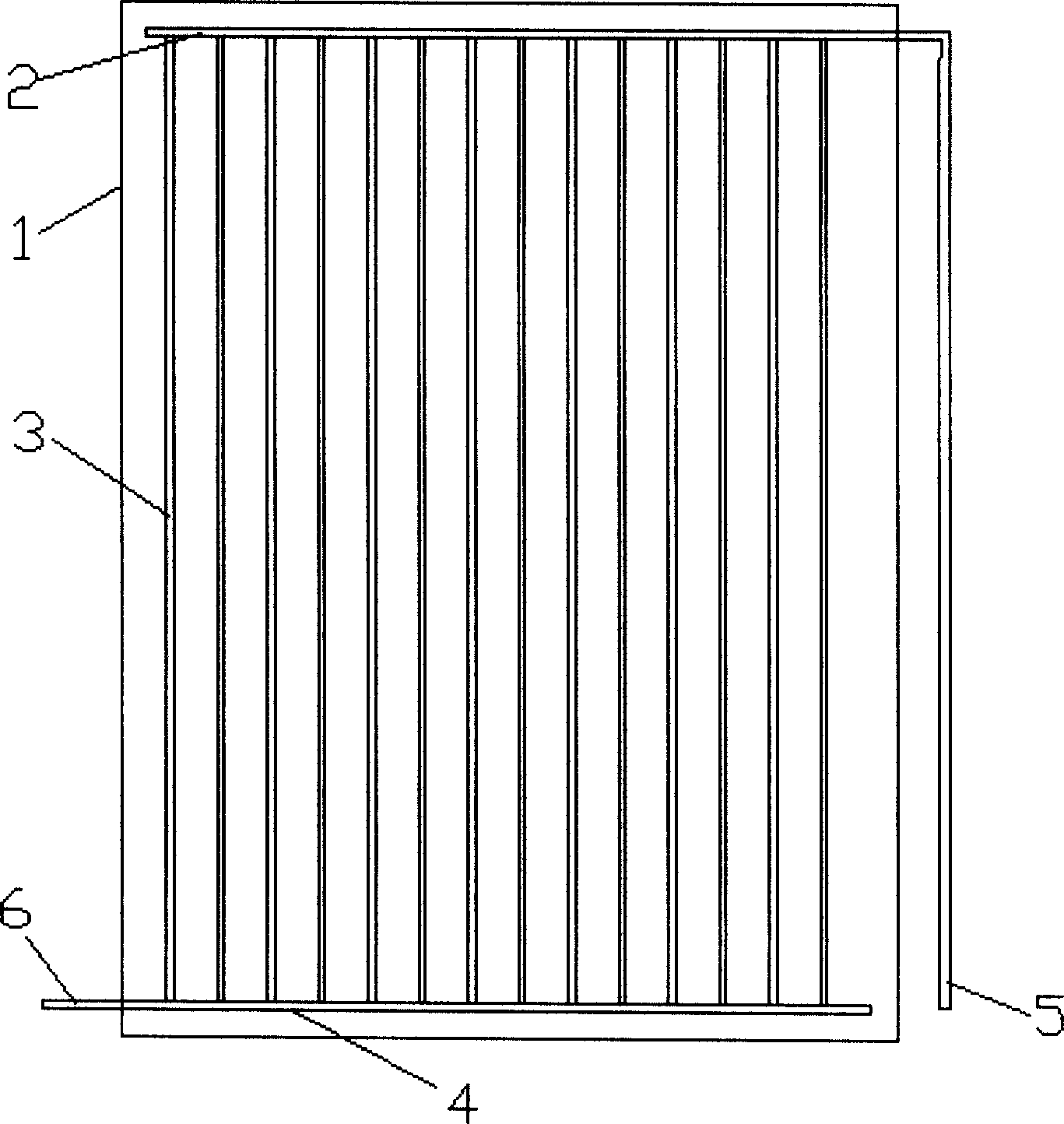
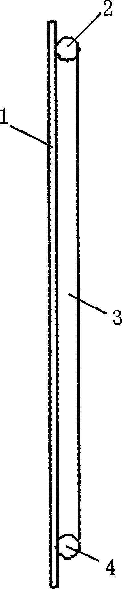
[0011] Such as figure 1 As shown, the condenser is composed of a set of parallel vertical pipes 3, an upper liquid collecting pipe 2, a lower liquid collecting pipe 4 which are respectively connected to the two ends of the vertical pipe, and a radiating plate 1 arranged on one side of the vertical pipe. The diameter of the vertical pipe 3 is generally 1 to 3 mm, and the thickness of the heat dissipation plate is 0.5 to 1 mm. After connecting the vertical pipe to the upper and lower liquid collecting pipes, glue it on the heat sink or fix it in other ways.

[0012] The working process is as follows: the refrigerant enters the condenser from the vertical pipe inlet 5, then enters the upper collecting pipe 2, and then is distributed to the vertical pipes 3. The refrigerant condenses in the vertical pipes and transfers heat to the heat dissipation th...


PUM


Abstract

The condenser for refrigerator consists of one group of parallel vertical pipes of diameter 1-3 mm, upper and lower collecting pipes communicated with the upper ends and the lower ends of the vertical pipes separately, and heat dissipating plate adhered to one side of the vertical pipes. The present invention has small size effect raising heat exchange, reduced flow pressure drop caused by the combined vertical pipes and collecting pipes, reduced compressor load and raised performance coefficient. The present invention is superior to available coiled pipe condenser and has reduced pressure drop, raised heat exchange, saving in material, low cost, simple first and improved technological performance.

Description

Technical field [0001] The invention relates to a condenser for a refrigerator, which is used for refrigeration appliances such as household refrigerators and commercial freezers, and belongs to refrigeration equipment [0002] Technical field. Background technique [0003] Most of the existing refrigerator condensers use coiled tube (coiled tube) or heat pipe type condensers. This type of condenser has the disadvantage of large pressure drop due to the long pipes, and the heat dissipation effect is not good. [0004] The Chinese utility model patent (Patent No. 90205345.0) discloses a heat pipe condenser, which has a complicated structure and high cost due to the need to add heat pipes. The Chinese Invention Patent Publication (Publication No. 1240922, Publication Date: 2001.12) discloses a coil type condenser. Although a long enough pipe is used to radiate heat, it brings a large pressure drop and causes compression. The pressure at the end of compressor compression increases, ...

Claims


Application Information

Patent Timeline
Patent Type & Authority Applications(China)
IPC IPC(8): F25B39/04F25D11/00
Inventor 李俊明李红旗张会勇
Owner TSINGHUA UNIV
Why Eureka
Try Eureka