Forming method of flexible optical fiber ribbon and dispensing equipment for implementing forming method

A molding method and technology of optical fiber ribbon, applied in the field of optical fiber, can solve the problems of discount of bending performance, reduction of fusion splicing efficiency, inability to achieve high optical fiber density, etc., and achieve the effect of improving strength, improving reliability, and improving optical fiber density.

Active Publication Date: 2022-03-22
YANGTZE OPTICAL FIBRE & CABLE CO LTD
View PDF11 Cites 0 Cited by
  • Summary
  • Abstract
  • Description
  • Claims
  • Application Information

AI Technical Summary

Problems solved by technology

The density of this cabled optical fiber cannot be very high, and the bending performance will be greatly reduced
The optical fiber cable in the form of loose fiber can achieve a relatively high fiber density, but it needs to be fused one by one during fusion splicing, and the splicing efficiency is greatly reduced

Method used


Image

  • Forming method of flexible optical fiber ribbon and dispensing equipment for implementing forming method
  • Forming method of flexible optical fiber ribbon and dispensing equipment for implementing forming method
  • Forming method of flexible optical fiber ribbon and dispensing equipment for implementing forming method

Examples


Embodiment Construction

[0035] In order to make the object, technical solution and advantages of the present invention clearer, the present invention will be further described in detail below in conjunction with the accompanying drawings and embodiments. It should be understood that the specific embodiments described here are only used to explain the present invention, not to limit the present invention. In addition, the technical features involved in the various embodiments of the present invention described below can be combined with each other as long as they do not constitute a conflict with each other.

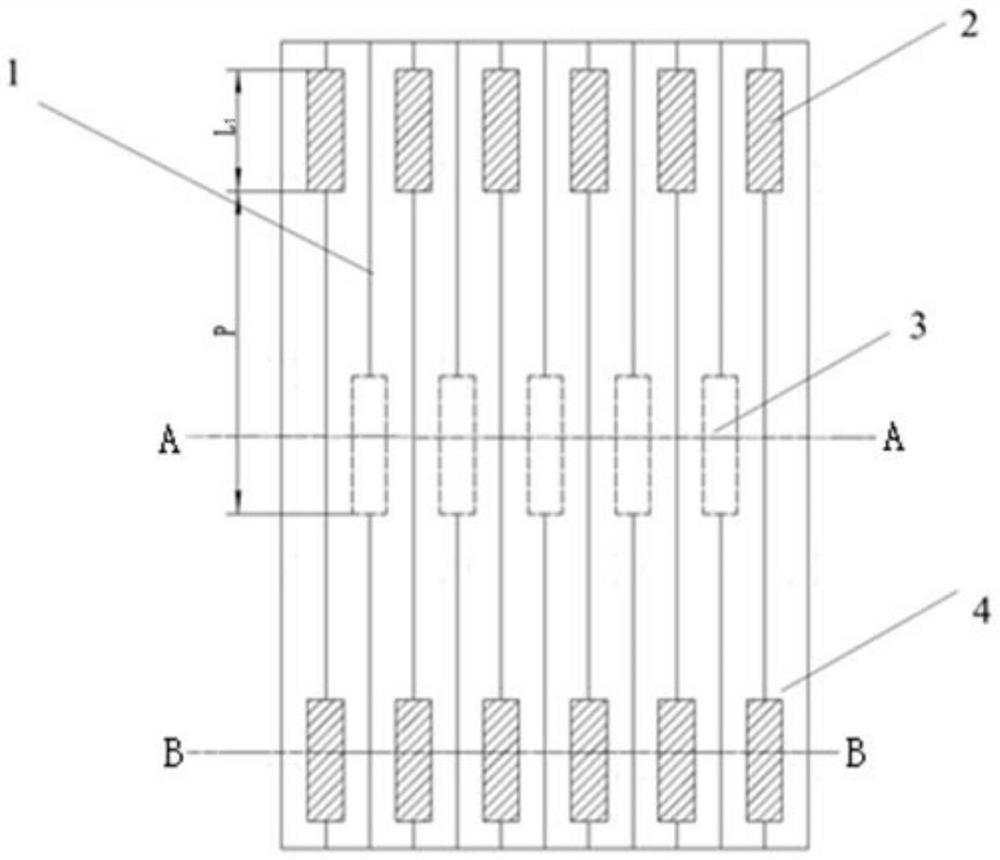
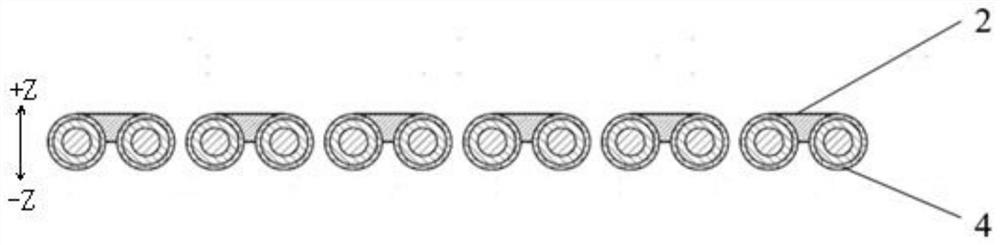
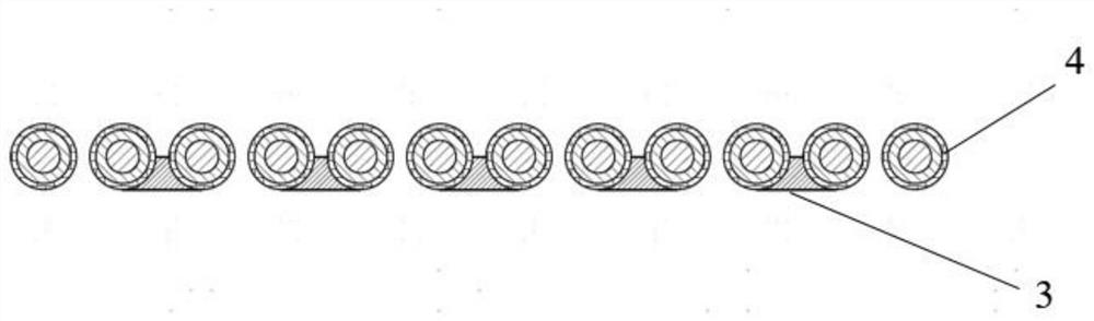
[0036] refer to Figure 1 to Figure 9 , a flexible optical fiber ribbon, including N optical fiber units 4 arranged side by side, any two adjacent optical fiber units 4 are preferably in contact with each other, and any adjacent kth and k+1th optical fiber units 4 pass through The first bonding part 2 is bonded, and any adjacent k+1th and k+2th optical fiber units 4 are bonded through the secon...


PUM

PropertyMeasurementUnit
viscosityaaaaaaaaaa
elongation at breakaaaaaaaaaa

Abstract

The invention discloses a forming method of a flexible optical fiber ribbon, which comprises the following steps: 1) a plurality of optical fiber units advancing in parallel are respectively coated with coloring layers capable of mutually distinguishing colors through a coloring mold, and then the coloring layers on the optical fiber units are incompletely cured in a curing oven; (2) an upper glue outlet unit and a lower glue outlet unit of the glue dispensing equipment respectively drop a bonding material B into a gap between the optical fiber units from the upper side and the lower side of the optical fiber units; and (3) the bonding material A, the bonding material B and the coloring layer are gradually cured, the adjacent optical fiber units are connected together through a first bonding part and a second bonding part which are formed through curing, any two adjacent optical fiber units are not bonded any more through curing of the coloring layer, and therefore the positions without the first bonding part and the second bonding part can be separated. The flexible optical fiber ribbon has good bending performance in the downward direction and the upward direction, attenuation of side fibers of the flexible optical fiber ribbon is small when the side fibers are stressed, and improvement of the optical fiber density of the optical cable is facilitated.

Description

technical field [0001] The invention belongs to the field of optical fiber, and more specifically relates to a flexible optical fiber ribbon, a molding method thereof and a glue dispensing device for implementing the molding method. Background technique [0002] With the advent of the 5G era, data has grown explosively, and massive amounts of data need to be realized in the form of dense networking. In the context of intensive and dense networking in data centers and computer rooms, the demand for large-core, ultra-high-density optical cables has emerged as the times require. Traditional large-core optical cables include rigid optical fiber ribbon cables (such as skeleton optical cables and layer-stranded ribbon cables) and layer-stranded optical cables in the form of loose fibers. Rigid optical fiber ribbon cable has the characteristic that the whole ribbon can be welded, and the welding construction efficiency is high. However, the traditional optical fiber ribbon cable ...

Claims


Application Information

Patent Timeline
Patent Type & Authority Applications(China)
IPC IPC(8): G02B6/44B05C5/02
CPCG02B6/448G02B6/4482G02B6/4486B05C5/0241B05C5/027
Inventor 黄俊高莹杨向荣祁林黄财明刘宏超阮云芳万秀强
Owner YANGTZE OPTICAL FIBRE & CABLE CO LTD
Why Eureka
Try Eureka