Large-current transmission connector structure based on spring

A connector and high-current technology, which is applied in the direction of connection, fixed/insulated contact components, circuits, etc., can solve the problems of difficult seal design for current transmission, small installation space, and large plugging force, etc., to solve the problem of large current transmission in a small space Difficult problems, strong overcurrent capability, and the effect of improving reliability

Pending Publication Date: 2022-03-22
CHINA ELECTRONICS TECH GRP CORP NO 14 RES INST
View PDF0 Cites 0 Cited by
  • Summary
  • Abstract
  • Description
  • Claims
  • Application Information

AI Technical Summary

Problems solved by technology

[0008] In order to solve the above-mentioned problem of reliable transmission of large current in a small space, the present invention provides a spring-based high-current transmission connector structure, which has good environmental adaptability, can ensure high-current sealing and reliable transmission, and effectively solves the problem of large-scale electronic equipment. The current transmission connector has a small installation space and a large insertion force, and solves the current transmission sealing design problem

Method used


Image

  • Large-current transmission connector structure based on spring
  • Large-current transmission connector structure based on spring
  • Large-current transmission connector structure based on spring

Examples


Embodiment Construction

[0024] A preferred mechanism and motion implementation of the present invention will be further described below with reference to the accompanying drawings and specific embodiments.

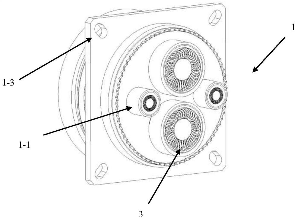
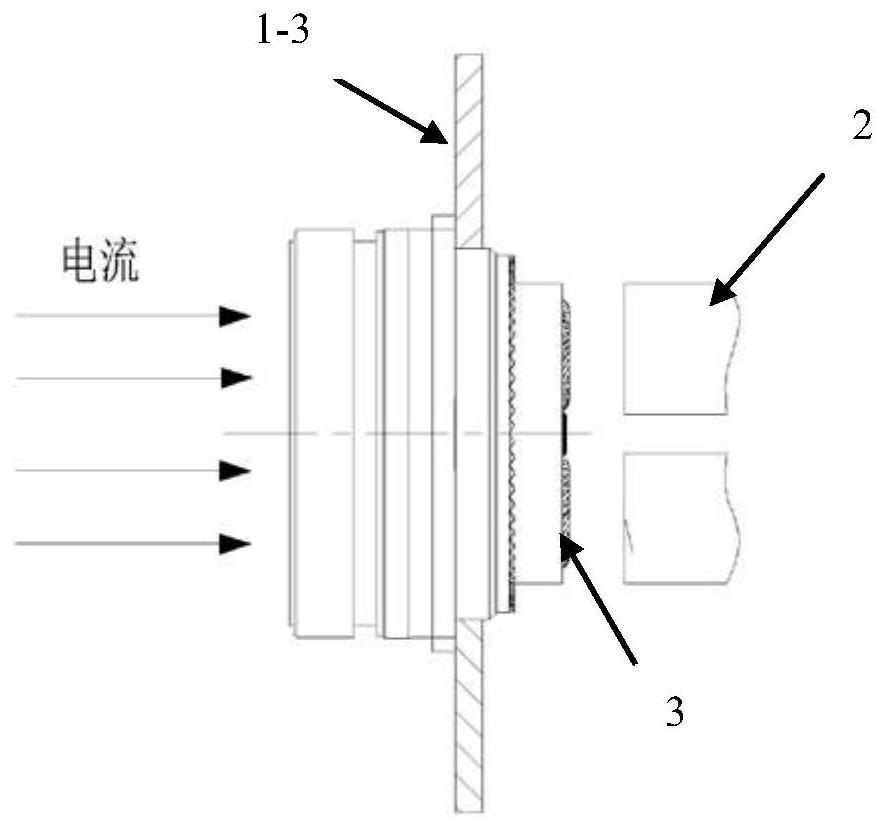
[0025] Such as Figure 1-6 As shown, it is a connector structure based on a spring-based large current transmission, the large current transmission connector, which includes a circular connector, including a connector plug end 1, and a connector tail end 2, the connector plug. The end 1 and the connector tail end 2 are mounted on the power supply device and the power supply device, and the connectors here can be another connector, or may be directly powered equipment.

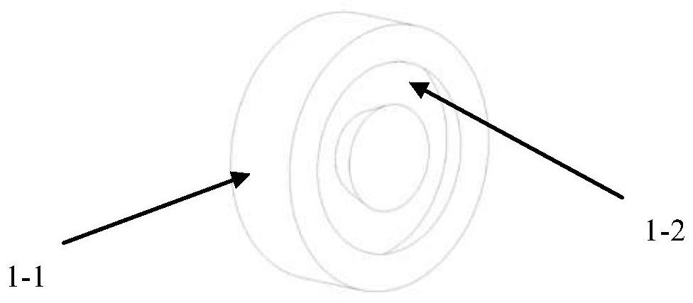
[0026] A plurality of terminals 1-1 are provided on the end face of the connector plug end 1, and an end surface of the terminal 1-1 is provided with an annular dovetail groove 1-2, and a ring-shaped coil spring is provided in the swallout tank 1-2. 3, the helical cross section of the annular coil spring 3 is an elliptical shape, the h...


PUM


Abstract

The invention belongs to the technical field of large current transmission, and discloses a spring-based large current transmission connector structure, which comprises a connector plug end and a connector tail end, a plurality of binding posts are arranged on the end surface of the connector plug end, annular dovetail grooves are formed in the end surfaces of the binding posts, annular spiral springs are arranged in the dovetail grooves, and the annular spiral springs are arranged in the dovetail grooves. The spiral cross section of the annular spiral spring is oval, the spiral outer diameter of the annular spiral spring is larger than the depth of the dovetail groove, and the tail end of the connector makes contact with and extrudes the annular spiral spring to achieve large-current transmission. The annular spiral spring is used as a current transmission medium, the power supply contact pressure is kept basically unchanged through contact compression of the binding post and the end face of the tail end of the connector, the problem of compression abrasion is well solved, the reliability of a transmission link is improved, and large-current transmission is achieved.

Description

Technical field [0001] The present invention relates to the field of large current transmission technologies, and more particularly to a connector structure based on a spring-based large current transmission. Background technique [0002] With the booming technology of airborne electronic equipment integration technology, the environmental performance, spatial placement, and electrical performance of electrical connections are also increasing. Taking the airborne radar as an example, the current radar antenna array is moving rapidly toward high power, high integration, and thinning in the direction. The antenna array transmission current transmission requires up to 1000A, while the installation space is only 62mm × 62mm × 15mm (15mm 15mm) For the contact direction size). Not only that, but also need to ensure the reliability and safety of electrical connections in a harsh vibration, climate, and three anti-environment. [0003] The traditional large current transmission uses a bu...

Claims


Application Information

Patent Timeline
IPC IPC(8): H01R12/85H01R13/40H01R13/52
CPCH01R13/40H01R13/52H01R12/85
Inventor 向华平费莲周夕维陈腾飞
Owner CHINA ELECTRONICS TECH GRP CORP NO 14 RES INST
Why Eureka
Try Eureka