An electrical control box for engineering machinery

A technology for electrical control boxes and construction machinery, applied in the field of control boxes, can solve the problems of inability to extinguish spontaneous combustion flames and easily lead to greater risks, and achieve the effects of simple structure, risk avoidance, and improved fire extinguishing effect.

Active Publication Date: 2022-05-17
XUZHOU PAT CONTROL TECH
View PDF5 Cites 1 Cited by
  • Summary
  • Abstract
  • Description
  • Claims
  • Application Information

AI Technical Summary

Problems solved by technology

[0004] The purpose of the present invention is to solve the problem that there are a large number of electrical components inside the existing electrical control box. Although it can automatically cut off the power and give an alarm when there is a short-circuit spontaneous combustion in the electrical appliance, it cannot extinguish the spontaneous combustion flame in time, which is likely to cause greater risks. disadvantages, and proposed an electrical control box for construction machinery

Method used


Image

  • An electrical control box for engineering machinery
  • An electrical control box for engineering machinery
  • An electrical control box for engineering machinery

Examples


Embodiment 1

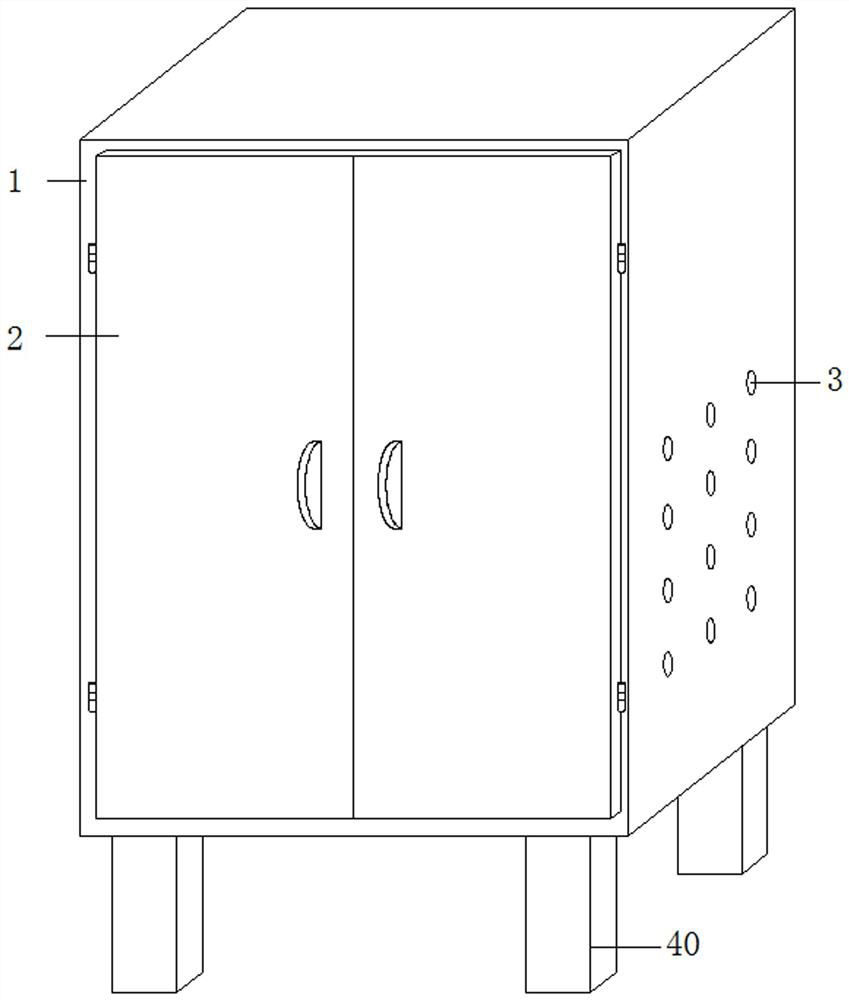
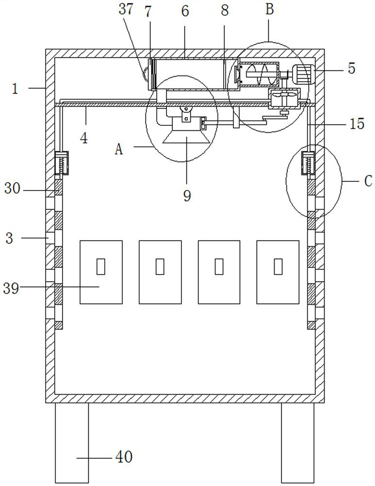
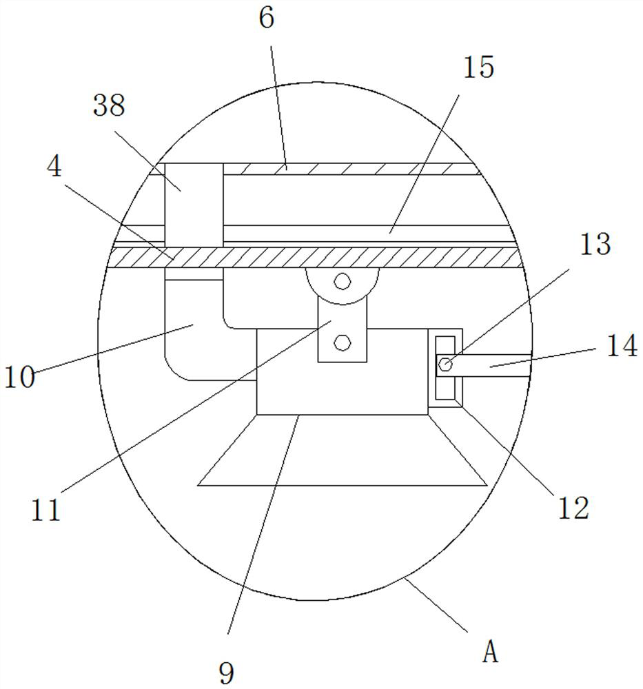
[0028] refer to Figure 1-Figure 6 , an electrical control box for engineering machinery, including a box body 1, four legs 40 are arranged at the bottom of the box body 1, electrical components 39 are arranged inside the box body 1, and two The box cover 2 and the rear side of the inner wall of the box body 1 are provided with a smoke sensor, and both sides of the box body 1 are provided with a plurality of cooling holes 3, and a support plate 4 is fixedly installed in the box body 1, and the bottom of the support plate 4 is rotatably installed with a Foam nozzle 9, foam tube 6 is installed on the top inner wall of box body 1, is provided with spacer 8 in foam tube 6, and servo motor 5 is installed on the right side inner wall of box body 1, and the output shaft of servo motor 5 is connected with Rotating rod 16, air cylinder 18 is installed on the right side of foam cylinder 6, and rotating rod 16 is connected with the rotation of air cylinder 18, and the outside of rotating...

Embodiment 2

[0039] refer to Figure 1-Figure 6 , an electrical control box for engineering machinery, including a box body 1, four legs 40 are arranged at the bottom of the box body 1, electrical components 39 are arranged inside the box body 1, and two The box cover 2 and the rear side of the inner wall of the box body 1 are provided with a smoke sensor, and both sides of the box body 1 are provided with a plurality of cooling holes 3, and a support plate 4 is fixedly installed in the box body 1, and the bottom of the support plate 4 is rotatably installed with a Foam nozzle 9, foam tube 6 is installed on the top inner wall of box body 1, is provided with spacer 8 in foam tube 6, and servo motor 5 is installed on the right side inner wall of box body 1, and the output shaft of servo motor 5 is connected with Rotating rod 16, air cylinder 18 is installed on the right side of foam cylinder 6, and rotating rod 16 is connected with the rotation of air cylinder 18, and the outside of rotating...


PUM


Abstract

The invention belongs to the technical field of control boxes, in particular to an electrical control box for engineering machinery. A large number of electrical components exist inside the existing electrical control box. Although it can automatically cut off the power and give an alarm when a short circuit occurs in an electrical appliance, The spontaneous combustion flame cannot be extinguished in time, which is likely to cause greater risks. The following scheme is proposed, which includes a box body, four legs are arranged at the bottom of the box body, electrical components are arranged in the box body, and the front of the box body rotates There are two box covers installed, smoke sensors are installed on the rear side of the inner wall of the box, multiple cooling holes are opened on both sides of the box, a support plate is fixedly installed in the box, and a foam nozzle is installed on the bottom of the support plate. A foam cylinder is installed on the top inner wall of the body, and a partition net is arranged in the foam cylinder. The invention has a simple structure, and can spray foam to extinguish the fire when the electric appliance spontaneously ignites, and at the same time can isolate oxygen to avoid greater risks.

Description

technical field [0001] The invention relates to the technical field of control boxes, in particular to an electrical control box for engineering machinery. Background technique [0002] The electrical control box is an important part of the host system of construction machinery. At present, the assembly space of the electrical control box of many models is small and the assembly efficiency is low. In addition, construction machinery vehicles are usually constructed in the field, and the electrical control box is generally assembled outside the body. Water vapor , dust, etc. are easy to enter the inside of the control box. There are many electrical control components that need to be assembled inside the box in the prior art, and the unreasonable layout makes it difficult to assemble the devices; in addition, because the devices are stacked and installed together, it brings great challenges to the maintenance personnel to detect and maintain the equipment. For example, the pub...

Claims


Application Information

Patent Timeline
Patent Type & Authority Patents(China)
IPC IPC(8): H05K5/02A62C3/16H05K5/06
CPCH05K5/0204A62C3/16H05K5/06H05K5/069H05K5/0213
Inventor 夏步林
Owner XUZHOU PAT CONTROL TECH
Why Eureka
Try Eureka